


Introduction
Eddy current technique is exceptionally important for reliable operation of aeronautical engineering. At the initial stage the eddy current technique was widely applied for surface defects detection. However, in the last decades it has been used for subsurface defects detection more and more, including fatigue and corrosive flaws in inner layers of multilayer aerostructures, defects under the layer of sealant, rivet head and etc.
Researches performed earlier in G. V. Karpenko Physical-Mechanical Institute of the National Academy of Sciences of Ukraine proved that it was possible to increase the testing depth due to the optimization of excitation field frequency and to the usage of eddy current probes (ECP) with spaced coils. The low-frequency eddy current flaw detectors, such as DUET, POLET, POLET-ZS, VID and VDN 1.01, where the testing depth is increased owing to the application of comparatively low operating frequencies, are developed on the basis of this research and ECP. There have been also elaborated effective techniques of eddy current testing of aerostructures, which can be easily adapted when using modern flaw detectors. The manual, issued in 2007, summarizes the experience of eddy current flaw detection usage while testing the aeronautical engineering units.
At present specialized low-frequency eddy current flaw detectors are not practically manufactured. Universal eddy current flaw detectors, which enable the testing in a wide range of frequencies, including low ones, were designed and produced at the end of the 80's of the past century. A possibility of various ECP connection makes the flaw detectors universal. The instruments provide an automatic compensation of ECP unbalancing and ECP signal viewing in complex plane (Х/У mode) or registration of real (vertical) or imaginary (horizontal) constituents of ECP signal in the mode of time scan (У/Т or Х/Т mode) on the display. At the same time, the possibility of turning the plane from 0 to 360° is assured for tuning out from interferences influence. Some universal flaw detectors had low-frequency and high-frequency filters with cutoff frequency adjustment option for reducing the interferences effect. The mode of bandpass filter was adjusted by simultaneous application of both filters and corresponding adjustment. This allowed the flaw detectors to carry put the inspection not only in static, but also in dynamic modes. Elotest В2 (Rohmann GmbH company, Germany) flaw detector was widely used in aviation. Due to the application of electron-beam tube for the display the instrument weight was rather big (11,5 kg). These instruments were purchased by the aircraft enterprises in the 80's of the past century and have been successfully used till now (for example, in the Kiev aircraft repair plant № 410 and at the "Borispol" airport).
Main requirements to universal eddy current flaw detectors
In recent years the universal eddy current flaw detectors have been considerably upgraded. The following capabilities are inherent to the majority of modern universal eddy current flaw detectors to this or that extent:
- application of digital technique of signal processing on the basis of the built-in processor or off-line personal computer;
- usage of fluorescent or liquid-crystal graphics (in some instruments - color) display;
- wide range of operating frequencies from hertz units to several megahertz;
- simultaneous usage of up to 4 operating frequencies (separately or in combination) in certain instruments ;
- usage of 2, 4 and more independent channels;
- possibility of testing in static or dynamic modes;
- possibility of various ECP connection (parametric, transformer, single, differential etc.);
- different modes of information display (complex plane, time scan, etc.);
- flaw detector setup automation and an option of flaw detectors settings storage when carrying out certain testing techniques to facilitate and speed up the setup;
- automatic going-off of the flaw detector alarm when a signal locus enters the window of complex plane, which boundaries and shape can be adjusted;
- possibility of received defectograms storing in files of standard formats (for instance, ТІF or ВМР) and their transmitting to PC or printer via different ports for saving and registering the testing results;
- possibility of integration in automatic testing systems;
- instrument embodiment in manual variant with self-contained power supply.
"Promprylad" SPC posed and solves the task of domestic universal eddy current flaw detector development, which would meet modern requirements by its embodiment. There are two variants of the instrument – ОKО-01 and Eddycon. The instrument ОKО-01 enables to solve a wide range of tasks and due to a large number of channels it is convenient in creating automated systems of (including complete) testing.
The capacities of simpler Eddycon are enough for the majority of eddy current testing tasks in aeronautical engineering (particularly in operation). Owing to small weight and dimensions as well to the presence of built-in storage battery, the instrument is especially convenient for usage in field and airfield conditions.
Specifications of ОKО-01 eddy current flaw detector
The concept of module principle of flaw detector construction was chosen when designing a universal eddy current flaw detector, meeting modern requirements. Such approach assures the possibility of flexible expansion of flaw detector capacities by connecting additional units and modules. A dedicated computer is the central module. Apart from the processor, membrane keyboard, TFT display, the central module contains a flash-card, which functions as read-only memory, encoder controller and USB port. The flaw detector controller allows the connection of two encoders, what is essential for providing a possibility to make the testing surface scan. The central module is connected to an eddy current unit by means of a special transceiver. The eddy current module is based on the erasable programmable logic device (ELPD). It runs the frequency synthesizer, amplifiers, compensation of ECP unbalancing voltage, ADC. Moreover, ELPD filters the received signal, controls external switches and prepares the pattern of eddy current signal for display on the central module screen.
It is possible to connect from 1 to 4 eddy current modules to ОKО-01 flaw detector; each module has one physical eddy current channel. Thus, one instrument can provide up to 4 independent eddy current paths. Each of these paths is able to operate in multifrequency mode. The values of operating frequencies are varied from 100 Hz to 2 МHz. ОKО-01 flaw detector can operate with different ECP (single, differential, parametric and transformer).
The instrument control keyboard is situated on the front panel of the flaw detector. The display presents the values of operating frequencies, sampling rate, exciting voltage, scale, turn. The flaw detector assures the signal view in complex plane, what enables to single out the signals against the background of interferences by analyzing the signal hodograph shape. Four signals on the (X/Y)-section of the display separately turn in the range from -360° to 360° with a step of 1 degree. Four working points of coordinates origin are independently located on the display. Image browsing allows to display up to 12 pages on the screen. Up to 4 eddy current channels can be displayed on each page. This allows configuring of up to 32 channels and easy flipping of 12 pages for quick viewing of all 32 channels of eddy current data. The sampling rate is adjusted by an operator and can make up to 1000 samplings per second at 4 frequencies. There is a possibility to set up to 4 alarm frames for each channel, which can be combined with the help of "AND" or "OR" logical functions.
Automatic measurement of the signal amplitude and phase assures the estimate of defect size while analyzing the data. The measured values of voltage phase and amplitude are essential for estimating the flaw size in accordance with the selected calibration curve. Such curve assures the association of the signal phase and amplitude parameters with the defect parameters in millimeters or per cent from the wall thickness.
Specifications of Eddycon eddy current flaw detector
Eddycon flaw detector (fig. 1) has one physical eddy current path, which ensures operation of up to 2 frequencies. The operating frequency range is chosen from 500 Hz to 6 МHz, what allows the connection of high-frequency and low-frequency ECP and the solving of tasks of surface and subsurface flaws detection. It is possible to work with single and differential, parametric and transformer ECP, manufactured by various companies, due to the adjustment of amplification and ECP exciting voltage.
The values of operating frequencies, sampling rate, exciting voltage, scale and phase (turning angle of complex plane) are displayed on the instrument screen. The image browsing enables to view 3 pages on the screen at a time. Each page displays 1 display area and 2 time scans. Every display area can display the eddy current signal in the following views: vector display of signals or complex plane. The sampling rate is adjusted by an operator and can make up to 3000 samplings per second. There is also the mode of automatic measurement of signal amplitude of phase for the defects of different depth with storing of the corresponding calibration curve, which is used for further estimate of the flaw size in the course of testing. Eddycon flaw detector provides for the creation of up to 4 alarm "frames" too. These frames and the signal together form an event (for example, threshold level exceeding by the signal). It can be indicted by the sound signal, LED illumination on the instrument panel, alarm by means of programmed indicators or the combination of the abovementioned reactions. The flaw detector is capable of mixing two channels. For mixing an operator can choose one of 5 algorithms: addition, subtraction, addition with horizontal inversion and addition with vertical inversion, product.

Fig. 1. Eddycon eddy current flaw detector view
Eddycon flaw detector filters the ECP signal in real time with the help of the following filters: low-frequency filter, high-frequency filter, bandpass filter, differential filter and averaging filter. The presence of filters permits to perform the mode of dynamic testing, which is rather prospective for detecting the flaws on the side surface of holes. There is a possibility of storing up to 100 flaw detector settings and 10 testing results, what enhances the operation efficiency.
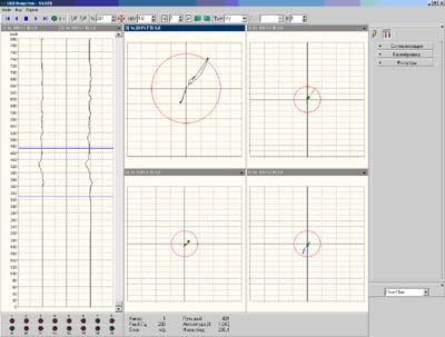
Рис. 2. Working field program to analyze the results of eddy current testing on the PC.
The testing data, received by this flaw detector, can also be transmitted to PC for long-term storage, processing, visualization, creation of databases on the tested objects (fig. 2).
Examples of flaw detectors application for the aeronautical engineering testing
As it has been mentioned above, the eddy current technique has no alternative when solving many aircraft tasks. The technique is especially efficient while detecting the flaws in multilayer aerostructures, the defects under the layer of sealant or paint, the flaws in holes, the flaws in the rivet area, including the area under its head etc.
The detection of hidden defects in multilayer aircraft units (or in testing from the unaffected side) is based on the usage of low-frequency ECP. There have been developed a set of low-frequency ECP for solving these tasks. The probes displayed great testing depth combined with good sensitivity and resolution. It is important that these ECP are well-tuned out from the influence of changes of the gap between ECP and testing surface. A set of special calibration blocks made from D16Т aluminum alloy have been developed and produced for metrological assurance during flaw detection of subsurface flaws. The block consists of two fayed parts. An extensive defect 2 mm in depth is simulated by a vertical joint of block parts. The indicated defect depth is 1 mm, 2 mm, 3 mm and 4 mm. It is possible to use the block for selecting an optimum operating frequency when detecting defects at a certain depth and for setting up flaw detector with the purpose of sampling flaws detection at a specified depth.
Let's consider several examples of prospective usage of universal flaw detectors for aircraft units inspection.
Testing of riveted joint area
An important advantage of eddy current testing techniques is the possibility to detect fatigue and corrosion flaws in internal layers of multilayered constructions, including its execution without fasteners dismantling and constructions disassembling. It allows to use efficiently eddy current technique of rivets area testing not only during repair of aeronautical engineering, when it is possible to dismantle fasteners, but also directly during tests and operation. Typical example of the simplest air two-layer construction where the stringer is jointed with the outer skin of an aircraft by a regular line of countersunk rivets is given in Fig. 3.
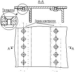
Fig. 3. Typical unit, such as "stringer-skin" with a rivet line.
The testing area is marked with a dash-and-dot line in Fig. 3. The position of possible crack is shown on the leader. The cracks which do not go beyond the rivet head are considered dangerous in many cases. In general, a number of jointed layers may be larger and defects can be located in inner layers.
The structural elements are jointed to the outer skin of an aircraft by countersunk rivets in the majority of cases. Internal joint is often performed with the help of rivets with heads of various shapes. Bolt joints are sometimes used, too.
According to the type of testing area scanning, all techniques of eddy current testing of rivet joints can be conditionally divided in three main groups:
- Static mode – carried out by placing ECP on the rivet or next to it;
- Sliding mode – performed by progressive ECP movement along the rivets line or near it;
- Rotary mode – ECP is put on the rivet and rotated around it manually or by means of a driver.
The modes of each group are used for the detection of flaws both in outer skin and in inner layers of multilayered constructions. In this regard, the techniques of each group have its merits and drawbacks. That is why, the possibility and efficiency of their application is determined by the features of aircraft constructions and required level of sensitivity and depth of testing.
The highest sensitivity is provided by rotary mode according to which ECP is placed in alignment with the rivet, unbalancing compensation is performed and the testing signal changes are observed when rotating ECP. The balance is kept when rotating ECP over the flaw-free rivet. If there is a defect, the balance is disturbed. For technique realization it is sufficient to provide rotation in both sides at an angle from 45 to 90 degrees. It is also important to assure the rivet and ECP centering.
For technique carrying out in case of countersunk rivets it is possible to use ECP of Leotest series with working area diameter from 7 to 15 mm depending on the rivet diameter. For ECP centering in this case dielectric guides with the hole of appropriate diameter are used. To detect defects under the rivets overhanging the testing surface and with round and cylindrical heads (head diameter - 10 mm, hole diameter - 6 mm), a special ECP of Leotest MDF 2201/10 R with central hole of corresponding diameter has been designed for its placement on the rivet. It should be noted that in this case it is not necessary to apply dielectric guides for ECP centering during rotation, as ECP is centered by the rivet itself. Special ECP of Leotest MDF 2201/10 R has been tested at the operating frequency of 2 kHz with signal registration in a complex plane. An experiment was carried out on the block from D16 aluminum alloy with 6 mm diameter hole from which artificial defects, such as cracks with opening of 0,1 mm, length from 1 to 6 mm (through 1,0 mm) was cut by electrospark technique. The block with a defect was covered with a flaw-free 2 mm thick plate with the hole of 6 mm in diameter and jointed by the rivet. Fig. 4-а and 4-b presents the hodographs of ECP signals received when turning ECP over the block with a crack of 1 mm (Fig. 4-а) and 2 mm (Fig. 4-b) in length. Having put ECP on the block, the unbalancing was compensated and complex plane was turned in such way so that the signal from defect was directed vertically from bottom to top. The sensitivity was the same during registration of signals from 1 mm long crack and signals from interferences. The sensitivity for 2 mm long crack was 12 dB less. Hodograph analysis shows that the crack length influences strongly the signal amplitude. In particular, the signal from 2 mm long crack is over 3 times more than the signal from 1 mm long crack. The signal from 1 mm long crack exceeds the level of signal from main interferences for more than 6 dB what proves high selectivity of testing with the help of presented ECP.
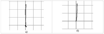
Fig. 4. Rotary ECP signals from defects, such as a crack of 1 mm (а) and 2 mm (b) in length under the rivet head and 2 mm thick skin.
Comparative study showed that the presented ECP has better sensitivity and selectivity while detecting flaws in the second layer from the surface than standard ECP intended for solving the same task.
Eddy current testing of air wheels
Nowadays there have been used a bulky and outdated instrument Elotest В2 to which MDF 0701 probes were connected for manual and automated testing. Eddy current flaw detectors, such as ОKО-01 and Eddycon complete with MDF 0701 probes, can solve this task even better. Upon that, ОKО-01 instrument is more effective for the development of automated testing system, and Eddycon instrument – for manual testing in airfield conditions. Fig. 5 presents the signals from defects with depth of 0,3 mm and 0,5 mm on ОKО-01 flaw detector screen. On the left there are signals on the time scan, on the right – signals in a complex plane. It is seen on defectogram that the signals from defect stand out well against a background of interferences (dependence of signal from smaller flaw and signal from gap change of about 10 dB).
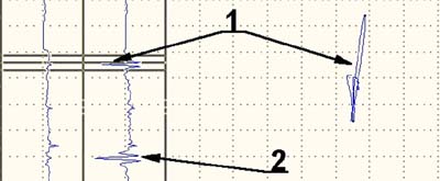
Fig. 5. Signal from defects, such as a crack, with depth of 0,3 mm (1) and 0,5 mm (2) in the air wheel hub.
Detection of defects under the layer of sealant.
The research performed by us showed that it is possible to provide a rather high sensitivity to fatigue cracks on the basis of low-frequency multidifferential ECP usage during testing through the layer of sealant (without its removal). The presence of sealant layer which has dielectric properties in the range of eddy current operating frequencies influences the same way as the gap between the probe and testing surface does. Distinctive feature of multidifferential ECP of Leotest МDF series is almost complete suppression of noises connected with the changes during inspection of the gap between the probe and testing surface. Dependences of ECP signal amplitude from defect when changing the gaps (or, in our case, the sealant layer thickness) are given in Fig. 6. For ECP of Leotest МDF 0901 type the dependence is got for two operating frequencies - 1 kHz and 10 kHz. The amplitudes of signals from through surface defect in 5 mm thick plate for different gaps are reduced to the amplitude of signal from the same defect during testing without a gap (layer of protective dielectric cover). For ECP of Leotest МDF 0701 type the dependence is got only for operating frequency of 10 kHz, as the frequency of 1 kHz lies beyond the operating range of this ECP. The mentioned dependences prove that for MDF 0901 ECP the signals from defect at the operating frequencies of 1 kHz and 10 kHz attenuate with the gap increase almost in the same way, i.e. the reduction of signal from defect with the gap increase depends only a little on its operating frequency. It is worth mentioning that this is applied to the case when the operating frequency is selected within an optimal range of operating frequencies of the present ECP. The comparison of dependence for MDF 0901 and MDF 0701 ECP shows that the attenuation of signal from defect with the gap increase depends more on its size. At the same time, it should be noted that attenuation difference is not significant and in many cases smaller dimensions of MDF 0701 ECP can give it an advantage during testing of complex aircraft units with projections, holes, fillet transitions etc. In general, it should be observed that for multidifferential ECP of Leotest МDF type the signals from coarse defects can be surely registered (with signal/noise ratio of more than 6 dB) at gaps of up to 15,0 mm for MDF 0701 ECP and at gaps of up to 10,0 мм for MDF 0701 ECP.
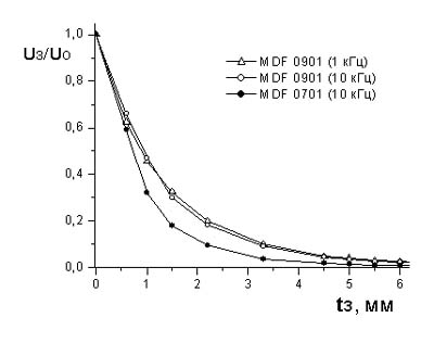
Fig. 6. Dependence ECP signals amplitude from the couplant layer thickness.
When detecting cracks under the layer of couplant, the critical areas are singled out; its list is determined by the design manager. First of all, these are the reinforcement sheet in places of skins and stringers joining, areas of stringer coarse thinnings in the zone of their end, bolt joints areas etc. In consequence of these areas analysis, there have been already developed the technique of detection of fatigue cracks in critical areas without removing the sealant which proved its efficiency in the aircraft repair enterprise conditions. Here is an example of critical area.
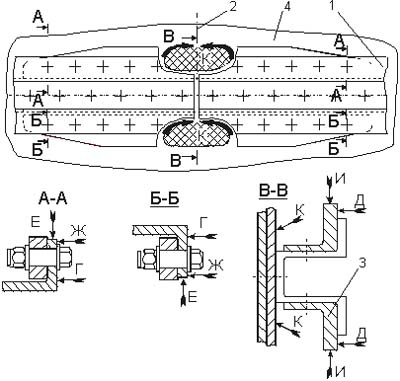
Fig. 7. Scheme of eddy current testing of stringers joint: 1 – stringer, 2 – stringers joint, 3 – reinforcing rib, 4 – skin.
Fig. 7 presents the scheme of testing of joint 1 with reinforcing rib 3. The layout of rivets and bolt joints are marked with crosses in this figure. The areas subject to inspection are marked with arrows, brackets with arrows and hatched sections with arrows. To make it simple, the sealant layer is not shown in the figure. The testing sections are divided into characteristics areas which are called "separate testing areas" (SRA). Flaw detector setup and operation procedure in each of these areas are different. The following characteristic sections are inspected on such unit: upper flanges of stringers 1 at rib ends (SRA are marked by the letters Г, Ж and Е), skin 4 in the area of stringers 1 joint 2 (hatched SRA – K) and reinforcing rib 3 in the area of stringer joint (SRA is marked by the letters И and Д).
Conclusion
The presented universal eddy current flaw detectors, such as ОKО-01 and Eddycon, which allow to solve a wide range of NDT tasks on the basis of possibility to operate in a wide range of operating frequencies. It is possible to present signals in a complex plane or signals components with time scan in flaw detectors. The filters of different kind can be applied as well what permits to improve signal/noise ratio while detecting small and deeply seated flaws (in nonmagnetic alloys). Flaw detectors enable to connect different ECP. The instruments provide the storage of setups and testing results. Due to small weight and dimensions and to the presence of built-in storage battery, such instrument as Eddycon is convenient for the usage in field and airfield conditions.
Flaw detectors, such as ОKО-01 and Eddycon, have sufficient sensitivity when connecting low-frequency eddy current probes. This allows to detect not only surface, but also subsurface flaws, including in multilayer aerostructures.
A special calibration block with internal flaws of depth from 1 to 4 mm have been designed for metrological assurance of eddy current techniques of hidden subsurface defects detection.
On the basis of Eddycon and ОKО-01 instruments with the application of special multidifferential ECP of Leotest series there can be developed the techniques of field inspection of aerostructures solid units, including:
- detection of local corrosion damages (including in "stringer-skin" area) while testing from the unaffected side;
- detection of fatigue cracks under the skin with thickness of up to 10-12 mm;
- detection of cracks in critical areas under the sealant layer with thickness of up to 15 mm, including in the caisson tanks;
- detection of cracks on the side hole surface;
- detection of cracks in aircraft wheel hubs;
- detection of cracks which doesn't go beyond the rivet head (including in the second and third layers);
- detection of cracks under the layer of chromium with thickness of up to 200 ?m in shock absorbers gears.