Visualization of the rail ultrasonic testing results — it is a key to a correct assessment of their condition
Introduction
One of the rail track ultrasonic testing (UT) features compared to the UT of another objects of the railway transport is its multi-channeling at a variety of sounding schemes, and a large extension of the TO. As a result of this particular feature, it is more challenging for the operator to seize such volume of information in real time–the testing by the single-rail trolley UDS2-77 and double-rail trolleys UDS2-73, as a rule, is performed at a speed of 3-4 km/h–the operator's walking speed.
Classic variants of visualisation and problem of their application
The UT classic variant of a signal representation is the А-Scan (fig. 1, а), even if it has been adapted to the multi-channel testing–MultiA-Scan (fig. 1 b)–is suitable only for testing of small portions of the rail track. These presentations prevent an operator from viewing how indications are dispensed along the rail, as well as require the operator to be high-skilled, since they are far from being visual.
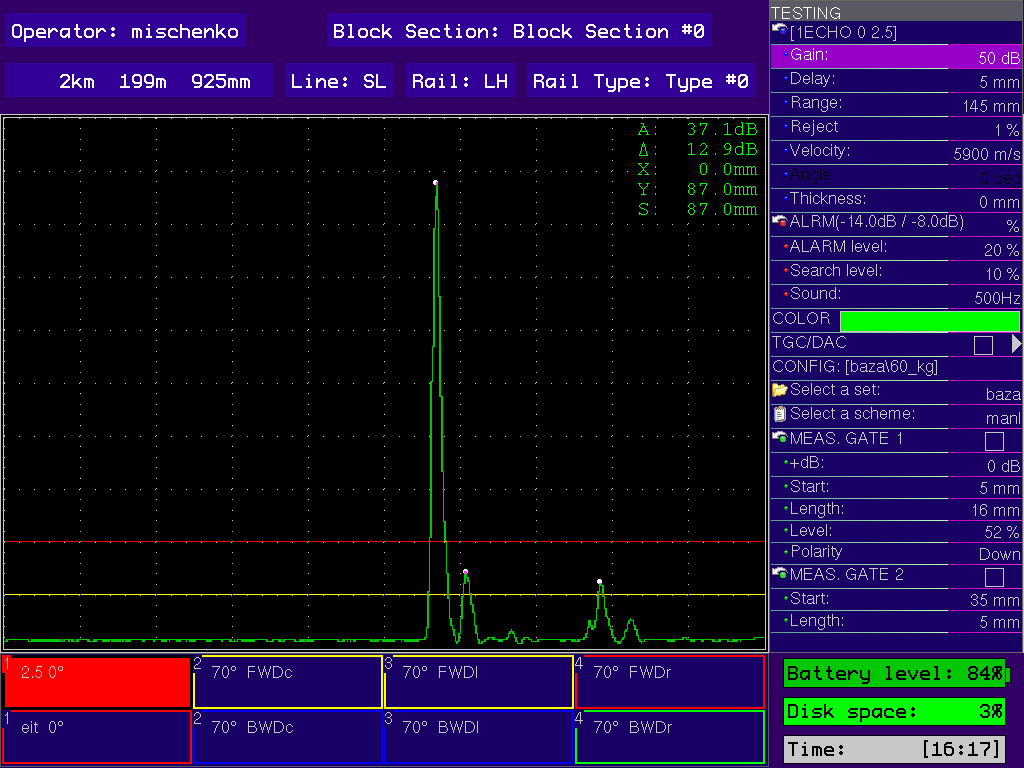
а) one-channel А-Scan
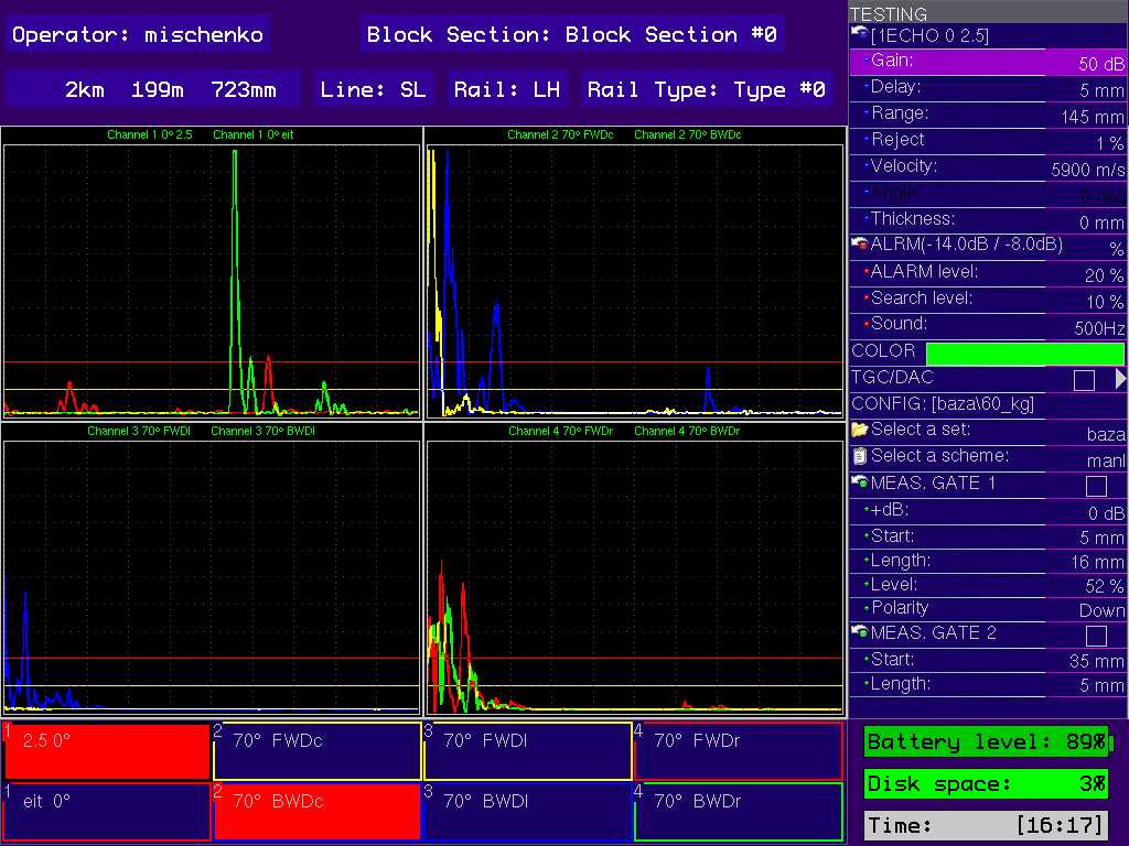
b) multi A-Scan
Nevertheless, they are the best solution to setup and calibrate the flaw detector. We added a function of a signal holding on the screen to the MultiA-Scan that facilitate perception of the indications a lot, even at a speed of up to 4 km/h.
Traditional solution: one-channel and line B-Scans
A problem of results review of the rails testing can be solved also due to B-Scan (fig. 2 a) application and frequently—in combination with the A-Scans (fig. 2 b). This type of signal display allows both to observe the "history" of testing provided for the past several meters on the B-Scan and to experience the dynamics of revealed indications using the A-Scan. However, the multi-channel testing is not taken into account in this case, as this kind of representation can be displayed only for one probe—the selected one.
а) B-Scan by one channel
b) А-Scan+B-Scan by one channel
As a result, most companies-manufacturers implement in their products so-called "line" B-Scan instead of the ordinary one (fig. 3). Here the B-Scans are grouped in lines by channels that correspond to some portion of the rail track under the test. For an experienced operator this type—including its combination with the А-Scan according to a specific channel or the Multi А-Scan—is quite convenient, but still not that visual.
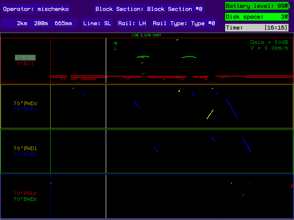
Figure 3 — Signal display mode in the form of line B-Scan
1 line — central cross-section of the rail (Example: 0°, 45° Probes)
2 line — central part of the rail head (Example: 70° Probe FWD C , BWD C)
3 line — gauging face of the rail head (Example: 70° Probe FWD L(GF) , BWD L(GF))
4 line — field face of the rail head (Example: 70° Н Probe FWD R(FF) , BWD R(FF)
Maximum intuitive perception: Natural Multi B-Scans with visualisation on the rail cross-section
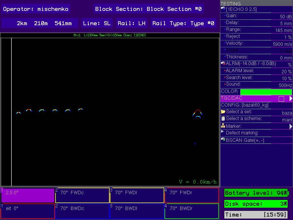
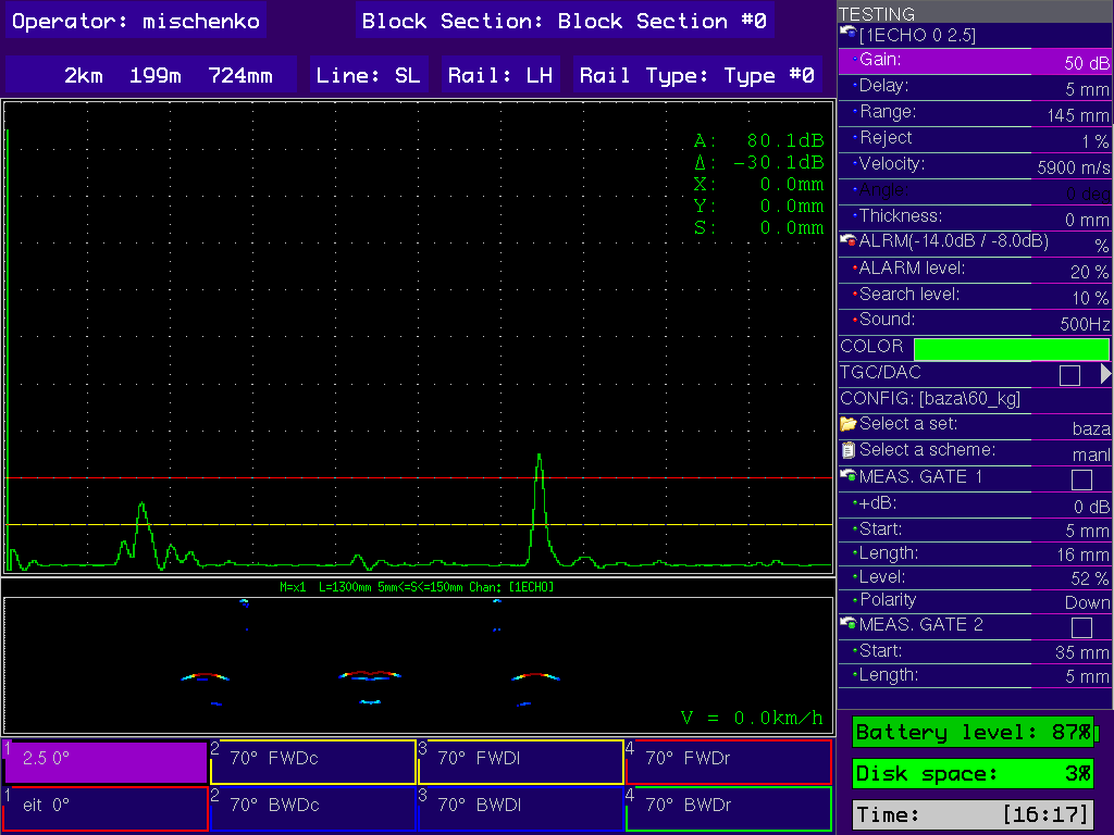
To increase visuality of the indications display in the multi-channel mode, we developed and implemented in our flaw detectors two additional modes: 1.NaturalMultiB-Scan (fig. 4 а); 2. NaturalMultiB-Scan+MultilineA-Scan (fig. 4 b), where the indications from all the channels simultaneously are displayed at their natural depths on the B-Scan with a possibility of the signals visualisation on the Multi line А-Scan. We will also implement the visualisation of the indiations detected on the rail cross-section (fig. 5 b).
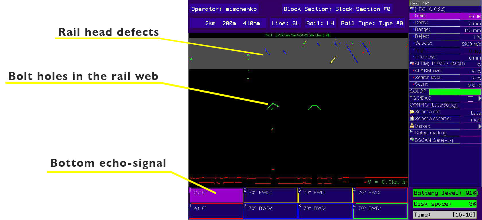
а) Natural Multi B-Scan

b) Natural Multi B-Scan+MultiLine A-Scan
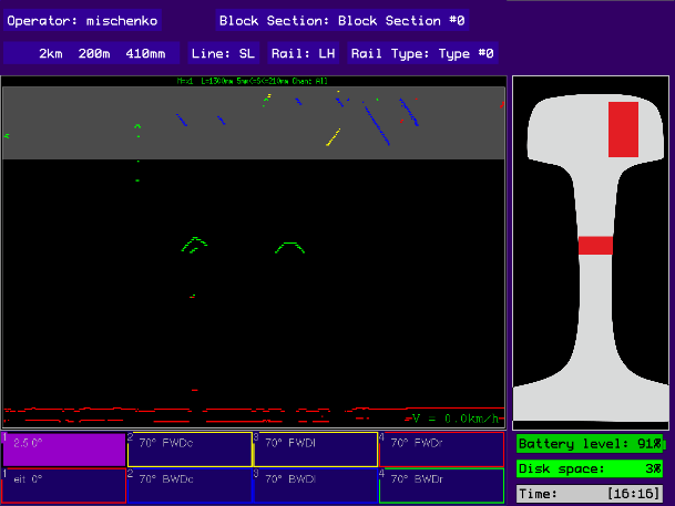
Figure 5 — Signal display in Natural Multi B-scan modes
This type of representation is maximum intuitive and is apprehended even by an unexperienced operator, that decreases much the percentage of error in assessment of the revealed indications, and decreases safety of the railway traffic.
Testing with the sound is more entertaining
Human's ear is capable of easy distinguishing millions of sound patterns. That is why, it is not an undertaking for the operator to get used to a specific sound code of indications within several days, and react to their detection, although one missed the defect in the visual sense.
Panel of channels–a quick changeover to assessment
At the indications detection by one or several channels, the corresponding field on the panel of channels is lit in red thus indicating which channels detected an indication.
Our Customers' experience
The majority of our customers use Natural MultiB-Scan or line B-Scan with sound in the process of testing. At the defect ALARM triggering for the concerned channel, they are switched by pressing a couple of keys to the B-Scan+А-Scasn (fig…) in order to review the indication in details and assess it. Then, they switch back to the multi-channel mode and continue testing.