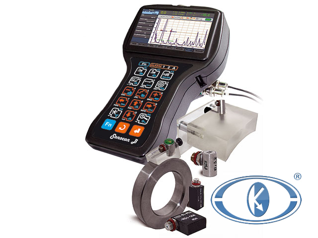


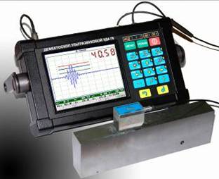
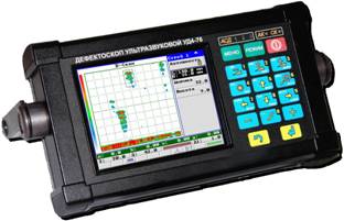
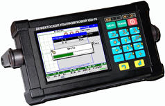
UD4-76 universal ultrasonic flaw detector-tomograph with large high-contrast TFT display is intended for products testing for detection of defects, such as discontinuity and inhomogeneity of materials, goods and in-process goods, weld joints, measurements of signals amplitude ratio from defects, of depth and their depth coordinates. Tomograph function allows to display and store testing results in the form of B-scans with affixment to scanning path. Flaw detector also solves the task of items thickness measurement at one-way access. Several operating modes for DGS diagrams are provided too, what makes it possible to define conveniently and quickly equivalent defects dimensions.
UD4-76 universal ultrasonic flaw detector is adapted and totally meets the requirements of regulatory documentation valid in various industrial sectors, such as: nuclear power engineering, metal production, pipe industry, rail transportation etc.
FLAW DETECTOR ADVANTAGES
For carrying out the testing of different parts, an individual approach is required for solving each separate task. "Promprylad" scientific production association has great experience in this field and offers the customer:
- special operating modes performed on the basis of the instrument software package and adapted to the customer's needs (among them there are: "Peak" mode, "Reflections marking" mode, automatic algorithms of probe calibration, modes of automatic DGS-diagrams and TCG-curves plotting, data storage in the form of RF B-scan, rendering of "corrosion map" ("thicknesses map") and other);
- flaw detector ergonomics when working with the object (large high-contrast TFT-display, small instrument weight, convenient menu, presence of automatic sound and light alarm of defects at three levels: search, registration, acceptance);
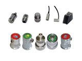
- individual delivery set which includes the set of ultrasonic probes adapted to the testing of the customer's objects.
FLAW DETECTOR DISTINCTIVE FEATURES
- Large color high-contrast TFT display.
- Metal protective case.
- ALARM system: 3 three-color LEDs, sound alarm.
- Convenient menu navigation.
- Various probes types operation.
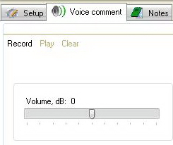
- Possibility of sound comments creation for all stored data types.
- USB slave.
- Encoder connection.
- Software application for different testing tasks.
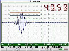
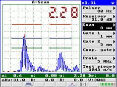
- Various A-scan display forms: RF/full wave/+half wave/-half wave.
- Dynamic change of generating path characteristics depending on the switched-on frequency filters.
- Information display forms: А-scan, B-scan, orthogonal views, corrosion map.
INSTRUMENT SERVICE FUNCTIONS
- Availability of two independent measurement gates with the defect alarm system (sound and light) by every gate. With that, every gate has:
- - three going-off levels: "ACCEPTANCE"; "REGISTRATION"; "SEARCH"; are marked on flaw detector screen in "RED", "BLUE" and "GREEN" color. The colors of light ALARM by every gate correspond to them;
- - the sound alarm going-off level is set up by an operator by a specific gate;
- - the mode (when the preset level is transcended or not) is set up by an operator for every gate independently.
Application of three-level gates enables to estimate the risk of detected defects.
When using three-level gates it is possible to register echo-signals at different levels relative to the acceptance level. It will permit to record echo-signals from developing defects and monitor defects in the program of testing results viewing what is necessary for carrying out ultrasonic testing (UST) of important objects. Three-level gates as well as convenient sound and light defect alarm system allow to assess the detected discontinuity dimensions quickly and qualitatively.
Time control gain
TCG level is set up in the point grid connected by linear sections, i.e. it is possible to set sundry TCG curve forms – piecewise-linear, step etc. TCG level corresponds to the signal attenuation in the given point relative to the set gain value. This option allows to test long-length items and items made from materials with great attenuation, it is also used for sensitivity setup when testing weld joints with wall thickness of more than 12 mm.


DAC amplitude curves mode
DAC mode is an alternative to TCG mode and enables to plot the curve which connects points (corresponding to signals peaks) on the screen, and also to plot up to 2 additional curves which is the preset value dB distant from the base one. DAC mode also allows quick and convenient TCG curve plotting.
«REFLECTIONS MARKING» mode
It helps to imagine the detected defect location in the testing item in the same direction as ultrasonic beams (straight, once- and multiple-reflected beam).


«PEAK» mode
It is indispensable during small defects search, operation in unstable acoustic coupling conditions. Upon that, the current signal value is displayed on the screen concurrently with the max. signal envelope of all observable echo-signals (displayed in red color). This mode is applied for max. echo-signal amplitude determination and conditional length estimation. It can be used for testing results registration both for rejected and in-order items, what will confirm the presence or absence of defects throughout the whole scanning perimeter.
Thus, "Peak"
mode application increases results reliability and reduces testing time.
Measurement of equivalent defects dimensions (DGS diagrams)
Using DGS diagrams UD4-76 flaw detector enables to measure equivalent defects dimensions in the range from 0,8 to 20,0 mm (equivalent defect diameter) with relevant error which does not exceed 15 %.
Availability of the algorithm (built in flaw detector software)
of automatic plotting of DGS diagrams for various probes types makes it possible to analyze the received data quickly and qualitatively and determine
equivalent dimensions of the detected discontinuities with their further registration. To save the time which is used for the instruments setup, UD4-76
instrument software contains the function of automatic TCG curve plotting by DGS diagram plotted for a specific probe.
")

Rendering of «corrosion map» – «thicknesses map»
To carry out thickness measurement as well as flaw detection of weld joints heat-affected zones, special modes are developed. These modes allow to perform flaw detection and thickness measurement of the testing area by means of the trolley where the probe is fixed. At the same time, the scanning path coordinates are fixed with the help of encoder and the received data are processed, whereby it is possible to get the profile of surface containing all possible discrepancies by metal thickness, delaminations and pitting damages.
RF signal display
To measure precisely the item thickness and defects coordinates, the undetected RF (radio frequency) signal is used what enables to assure the measurement resolution of 0,01 mm. Two modes of the point selection on the signal oscillogram by which the measurements are taken (automatic and manual) are provided in the instrument.

SAFT mode
To receive more accurate testing results, a special program application which performs SAFT algorithm for the usage of weld joints and steel workpieces in flaw detection is developed. This algorithm permits to get higher value of "signal/noise" ratio (even during testing of objects made from coarse materials) during data processing and reproduce an approximate defect form.
Special program interface mode
This mode is applied for solving special-purpose tasks. For example, when testing various single-type parts or when the part has many testing area. For solving this task "Special program interface" system is used in UD4-76. The necessary standard setups and program interface of "Special program interface" enter flaw detector from PC. The input setups are protected from illegal change by NDT inspector (operator).
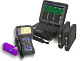
Mode of connection to PC
Is essential for data transmission from the flaw detector memory to the computer memory and vice-versa. It is used for transmitting "А-scans"and "B-scans" to PC for reports creation on the basis of testing results or databases. If required, the user can input setups for specific testing types in flaw detector from PC via in-built USB port what considerably reduces the time of flaw detector preparation for testing execution.
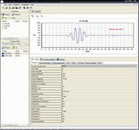
Software
Ultra UDх-7х – the program intended for processing testing results of UD4-76 ultrasonic flaw detector and serves for functionality extension and increase of instrument operation comfort. The present program assures operation with the data stored on PC.
Memory elements operation enables to perform the following functions:
| view: setups, А-Scans and B-Scans; | processing and measurements: B-Scans; | creation and editing: Setups. |
 |  |  |
| Reports printing by: А-Scans and B-Scans | |
 |  |
- Recording and listening to sound comments for: setups, А-Scans and B-Scans
 |  |  |
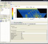
Viewing of Orthogonal B-Scans views
Projections permit to imagine the detected defects distribution.
Besides signal amplitudes and distance along the beam, flaw detector also saves the probe position coordinates in the moment of defect detection. Software calculates 3-dimensional coordinates of every indication basing of the stored data and setups of flaw detector. As a result, it becomes possible to build 3-D scan or, what is more informative, its orthogonal views.
Orthogonal B-Scan views can be used both for studying the detected defects distribution and for measuring their parameters and printing testing reports.
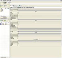
Measurements on B-Scans
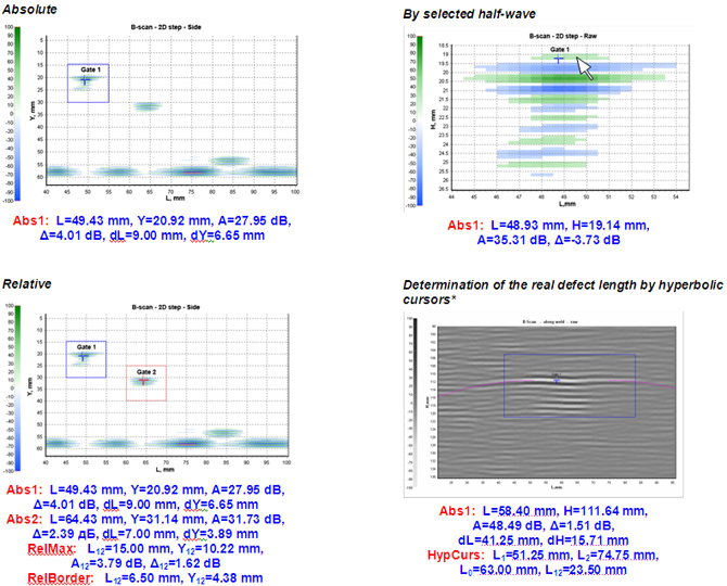
Absolute measurements allow to receive information about the next indication parameters:
- Coordinates:
- L – coordinate along the joint (Lstep – in case of step scanning), mm.
- X – horizontal coordinate across the joint, mm.
- Y – defect depth, mm.
- H – distance to the defect along the acoustic probe beam, mm.
- Amplitude characteristics:
- A – defect amplitude (gain at which the signal amplitude would correspond to 50% of the screen height), dB.
- Δ – exceeding of level 50% of the screen height by the signal amplitude, dB.
- Conditional dimensions:
- dL – conditional length.
- dX – conditional width.
- dY – conditional height.
During Relative measurements, in addition to the parameters described above, the following values are displayed:
- Conditional distances between the defects measured by the points of max. amplitude (RelMax) and relative to indications edges (RelBorder):
- L12 – conditional distance along the joint, mm.
- X12 – conditional distance across the joint, mm.
- Y12 – conditional distance by the depth, mm.
- Amplitudes difference:
- A12 – absolute amplitudes difference (taking into account TCG influence), dB.
- Δ12 – on-screen amplitudes difference (without taking into account TCG influence), dB.
Measurements by the selected half-wave (both absolute and relative) enable to increase considerably the accuracy of measurement of testing objects thickness and detected defects coordinates. They also add to the measurements accuracy using TOFD technique.
Measurements of the real defect length by hyperbolic cursors:
- are performed automatically – it is enough only to select the indication in frame or (for accuracy increase) to indicate the pulse;
- enable to clip "wings" of indication which are generated by the probe field and, thereby, to get coordinates of extreme defect points (L1 and L2) and its real length L12.
Probe direction pattern measurement *
Testing results interpretation based only on the refracted angle can lead to an error, as the influence of the width of main and the presence of side directional lobes of the probe are not taken into account. Ultra UDх-7х enables to take the probe direction pattern and measure its main parameters. For this purpose, one can use any B-Scan acquired by this probe and containing indication from the side drilling. Knowing the probe direction pattern form and its parameters it is possible to treat testing results with greater certainty.
| parameters | units | values |
| Max. scan range | inch | 236,22 |
| mm | 6000 | |
| Min. scan range | inch | 0,039 |
| mm | 1 | |
| Velocity in the material | inch /µs | from 0,0025 to 0,0375 |
| m/s | from 1000 to 15000 | |
| Scan delay | inch | 472,44 |
| mm | 12000 | |
| Delay (in the wedge) | µs | from 0 to 100 |
| Frequency | МHz | from 0,4 to 20 |
| Initial pulse frequency | Hz | from 30 to 1000 |
| Operating modes | А-scan, B-scan | |
| Gain | dB | from 0 to 100 |
| Signal detection | radio signal (without detection) full wave positive half-wave negative half-waves | |
| Noises cutoff | % | from 0 to 80 |
| Gates | two independent three-level measuring gates two additional special gates | |
| Measurement modes | Peak, Front | |
| Reconfigurable readings in А-scan | distance by the beam, amplitude in gates, defects depth coordinates, equivalent defect dimensions | |
| Measurement resolution | inch | 0,00039 |
| mm | 0,01 | |
| Defect alarm | sound, light, visual | |
| Setups quantity | at least 100 | |
| Languages and interfaces | English, Russian, Chinese (additional languages are possible to the customer's order) | |
| Units | SI system units | |
| Connection to PC | USB port | |
| Battery | storage battery Hi-MH 12V/2500 mА×h | |
| Operation time from the battery | hour | at least 8 |
| Power supply from AC network | single-phase network 230 V, 50 Hz | |
| Screen | color TFT | |
| Screen size, W x H | inch | 4,33 x 3,346 |
| mm | 110 x 85 | |
| Screen resolution, W x H | pixel | 320 x 240 |
| А-scan size, W x H x D | pixel | 320 x 200 |
| Overall dimensions | inch | 9,72 x 5,79 x 3,15 |
| mm | 247 x 147 x 80 | |
| Weight | lb | 7,717 |
| kg | 3,5 | |
| Operating temperature | ºF | from +14 to +122 |
| ºC | from minus 10 to +50 | |
| Protection from environmental impacts | IP 65 according to GOST 14254 |
| Name and description | Quantity pcs. |
| Electronic unit of the ultrasonic flaw detector UD4-76 | 1 pc. |
| Piezoelectric transducers (M8): - П111-2,5-К12-003 | 1 pc. * |
| Cable connection (PEP / electronic control unit) M8 × 2BNC | 1 pc. |
| Cable connection (PC / electronic control unit) USB | 1 pc. |
| Sync cable input | 1 pc. ** |
| Sync cable output | 1 pc. ** |
| Automatic charger Mascot Type 2015/td> | 1 pc. *** |
| Battery power supply | 1 pc. |
| AC Adapter BP-2 | 1 pc. ** |
| Headphones with Microphone | 1 pc. ** |
| Scanner RSP-4 | 1 pc. ** |
| Processing software testing results on a PC | 1 pc. |
| Manual UD4-76.23535778.04.01.06RE | 1 copy. |
| Manual Type 2015.23535778.002 RE | 1 copy. *** |
| User Guide Software for processing the results on a PC monitor | 1 copy. |
| Case for the electronic unit flaw UD4-76 | 1 pc. |
| Case for spare parts and accessories | 1 pc. |
| Calibration certificate flaw UD4-76 | 1 ind. |
* - Can change (or supplemented) by order of the consumer in the attached probe nomenclature. On delivery type converter cable P112 constructively can be included in probe.
** - Supplied upon request of the consumer.
*** - Type of charger may change.