


The need of non-destructive testing (NDT) application in aviation demands much of the equipment and technique makers qualification what is connected with a great variety of shape and complexity of testing units. Thereby, it is usually necessary to test the areas of stress concentration: holes for fasteners, panels edge, fillet transitions etc. In operation it is often essential to carry out NDT without removing the layer of paint-and-lacquer coating or sealant what excludes the usage of penetrant and ultrasonic techniques. In many cases there is no two-way access what makes it impossible to apply X-ray NDT technique. Moreover, it is often necessary to perform NDT in field conditions and airfield conditions. During field service of aircrafts an operator with the equipment should be located directly on the wing or stepladder.
That is why during aeronautical engineering maintenance the majority of inspection operations is executed by eddy current NDT technique. Eddy current technique is very important for aviation due to its exceptional advantages:
- possibility of holes side wall testing,
- possibility of uncleaned surface testing,
- no need to apply couplants,
- small dimensions and weight of equipment etc.
in aircraft skin with the usage of Eddycon flaw detector.
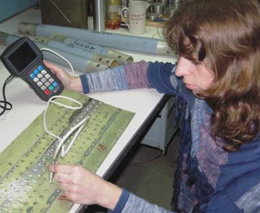
Fig. 1. Practicing of local corrosion damages detection technique
When detecting defects in the inner layer of multilayer aircraft parts, eddy current technique using low operating frequencies is totally unique. For the last decades a number of testing techniques have been developed. They include the detection of subsurface defects of corrosion and fatigue origin during the inspection from intact sheet side, defects detection under metal skin of different thickness (under repair plate included), defects detection under rivet heads [1]. For their implementation special low-frequency instruments which are widely used in aircraft industry have been designed. When universal eddy current instruments operating in a wide frequency range entered the market, there was no need to use special-purpose units any more, thus a lot of techniques can be easily performed with their help. Today, domestic Eddycon universal eddy current flaw detector has appeared in the market (fig. 1). Perspectives of this instrument for aviation are connected with a wide range of operating frequencies, a possibility of various eddy current probes (ECP) connection, great capabilities of signal registration and procesing, small dimensions and weight. The more so because flaw detector capabilities are constantly extending what will be shown below.
Let's examine several typical examples of Eddycon flaw detector application in aviation.
Defects detection under the skin.
Let's study the detection technique of defects in the form of through-thickness cracks between rivet holes in the bottom skin sheet (i.e. through 1,4 mm thick layer) (fig.1). The distance between the rivets edges is 8 mm. Calibration block (CB) for the technique practicing is given in fig. 2. On CB there are two testing areas: one area (to the left) corresponds to defect-free connection; another area simulates two-layer connection with the crack which goes between the rivets in the second layer. In this case the main interference is the influence of rivet and holes on ECP signal taking into account a close rivets spacing. That is why the testing technique should make it possible to single out signals from defects among the influence of signals from interferences caused by rivets.
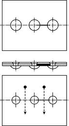
Fig. 2. Calibration block simulating two-layer rivet connection with defect.
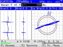
The conducted researches showed that application of MDF 0801 multidifferential ECP solves the present task the best [3]. Upon that, the diameter of operating ECP surface (8 mm) is rather small to scan the area between rivets. Testing technique implies the scanning of the area between rivets along the line perpendicular to the rivet line direction (shown in fig. 2 in a dotted line). Before carrying out inspection, one must perform ECP equilibration in the point which is situated at the distance of 10-12 mm from the line connecting rivets (shown in fig. 2 by a black circle). The signal is watched in the complex plane mode what allows to single out signals from defect in the bottom sheet from signals from interferences caused by the influence of rivets themselves. Fig. 3 presents ECP signal during the scanning of the area between rivets when there is no defect. The signal during the scanning of the area between rivets at the defects absence in case of the scanning line shifting in direction of one of rivets is shown in fig. 4. Fig. 5 represents the signal from defect. For better signals singling out the gain in vertical direction is 6 dB greater than the gain in horizontal direction.
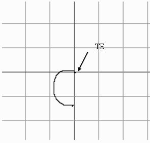
Fig. 3. ECP signal caused by the rivets influence during symmetric scanning.
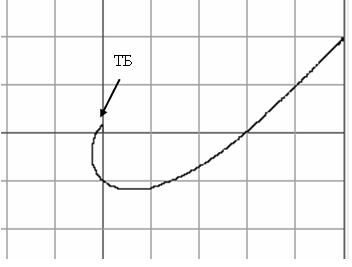
Fig. 3. ECP signal caused by the rivets influence during shifted scanning.
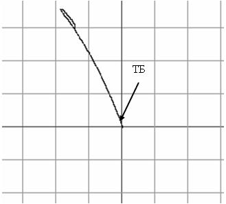
Fig. 3. ECP signal from defect.
It is seen on the defectogram that hodographs of signals from rivets in fig. 3 and 4 are plotted from equilibration point (BP in fig. 2-5) to the bottom part of a complex plane. At the same time, the hodograph of the signal from defect has another direction – to the top part of a complex plane (fig. 5). Possibility of signals singling out in a complex plane is improved by different gain in vertical and horizontal directions. The introduced defectograms show a possibility to single out clearly the signals from defect from the signals from rivets even if the testing area was carelessly scanned along the hodograph line in a complex plane.
Aircraft wheels hubs testing.
Detection of defects in hubs and flanges of aircraft wheels from aluminum and magnesium alloys is an example of successful eddy current technique application in aviation. The advantage of eddy current technique in comparison with dye penetrant flaw detection is defined by a possibility of cracks detection without removing oxide film, protective coating and paint [4]. Eddy current testing introduction enabled to increase the number of plane landings from 50 to 350 without inspection at many repair enterprises of civil aviation [4]. Slag and flux inclusions, oxide films and cracks are detected in cast hubs. Cracks and oxide films are detected in stamped hubs. At the first stages of eddy current technique introduction for hubs testing the defects have been detected in 6 % of items. Special attention is paid to the inspection of fillet transition and wheel hubs flange [1].
In accordance with the standard testing technique two scanning types are applied: circular and zigzag.
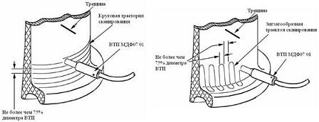
Fig. 6. Scanning schemes during wheels inspection.
When inspecting the wheels of С20295162 model of Airbus A320 airplanes produced by Messier-Bugatti by means of Eddycon flaw detector, the crack 30 mm in length and 0,52 mm in depth was detected under the layer of paint-and-lacquer coating (fig. 7). The crack was detected during circular scanning and confirmed by zigzag scanning (fig. 6). The crack was situated at an angle of 45° to circular scanning trajectory. MDF 0701 probe at operating frequency of 420 kHz [3] was used at testing. Flaw detector setups: Scond.1 = 15 dB, voltage on ECP Ugen. = 4 V, main scale = 0,6. Threshold level was set up for CB for 0,1 mm deep defect.
Fig. 7. Signal from natural 0,52 mm deep defect on the wheel.
Hole side walls testing.
One of the most important tasks for aviation is detection of cracks on hole side walls which are considered as hard-to-reach areas for direct testing, even if the fastener is removed. It is connected with relatively small diameter of holes (from 3 to 20 mm) at rather big depth. It sometimes happens that the fastener connects three and more structural elements. With that, materials may have different physical properties, and cracks are located in any layer. In such conditions the majority of existing techniques, for instance, ultrasonic, penetrant, magnetic and X-ray are either inapplicable at all, or ineffective. That is why, eddy current technique is recognized as the most efficient for solving this task. Nevertheless, there is a number of factors which complicate eddy current testing of holes side walls among which are: oval shape of hole, presence of marks from thread, notches, scratches, grooves etc. on the hole side surface, roughness of the hole side surface, presence of foreign particles or chips on it, skin edge impact and so on. The influence of the most mentioned factors is eliminated according to a specific technique. In this regard, all technologies can be divided in 2 groups. In the first case static flaw detectors are used [5]. In the second one – dynamic testing mode with the application of special-purpose rotary scanners which assure a rather high speed of internal hole surface scanning [1]. Dynamic mode provides the singling out of defect component in the spectrum of simulating ECP signal what gives additional possibilities for suppressing a number of interfering factors. It is possible to suppress efficiently the impact of ovality, skin edge, foreign particles presence etc. by the correct selection of filter parameters.
For solving these issues by means of Eddycon flaw detector it is necessary to develop effective rotary scanners operating as its component, to provide flaw detector scan phasing with rotor rotation and to make high-quality filters available. The last flaw detector upgradings by its design engineers were dedicated to solving of these tasks [6].
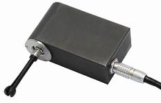
The rotary scanner and the signals received by means of the scanner and Eddycon flaw detector are presented in fig. 8. The results are obtained with the help of PN-04-TD01 ECP at operating frequency of 2,5 МHz. Flaw detector setups are the following: Scond. = 10 dB, voltage on generator ECP coil - 4 V, nominal scale - 4.0. The passband filter with pass band from 170 Hz to 400 Hz was applied. On calibration block in the form of a washer from D16 alloy with outer diameter of 24 mm, inner diameter of 9,5 mm and thickness of 6,5 mm artificial defects, such as cracks 0,2 mm in length and 0,2 mm in depth and defect 0,7 mm in length and 0,7 mm in depth (fig. 8 b) have been detected.
а
b
Fig. 8. Rotary scanner (а) and signals from defect on Eddycon flaw detector screen (b).
The scan which includes the signal display in a complex plane and its amplitude display by means of time scan was presented in fig. 8. Circular scan is built in such way so that each turn of rotary ECP corresponded to one scan cycle. The present scan type application enables to define an exact defect location in the hole.
As it was mentioned, it is very essential to have good filters for efficient operation of flaw detector in dynamic mode. Digital filters characteristics received at sampling frequency 1000 Hz are shown in fig. 9 and 10. In fig. 9 an average frequency ƒav of bandpass filter is 100 Hz, in fig. 10 – ƒav is 250 Hz. Horizontally, the frequencies from 0 Hz to half of sampling frequency are marked.
Fig. 9. Bandpass filter characteristics for ƒav= 100 Hz.
Fig. 10. Bandpass filter characteristics for ƒav = 250 Hz.
Filter characteristics have been obtained in the following way:
- Filter parameters (pas band) were set up manually;
- Frequencies from 1 Hz to Fd/2 Hz (500Hz) with a step of 5Hz were input by turns to the filtering unit with further measurement of the filtered signal amplitude (this operation was simulated on EPLED programmatically);
- Filtered signal amplitude was calculated as arithmetic mean of 200 measurements;
- Received data were stored in a text file on the instrument flash-card;
The presented characteristics of digital filters prove that they can be used for singling out of signals from defects especially among slowly changing signals from interfering factors.
Conclusions.
The submitted results show that it is possible to apply effectively Eddycon flaw detector for solving urgent NDT tasks of aeronautical engineering.
Products used for this application

Eddycon portable eddy-current flaw detector
Eddy current flaw detector Eddycon is referred to the testing and evaluation means.It is intended for manual testing by eddy current technique for the presence of surface and subsurface defects, such as discontinuity of the material (cracks, overlaps, holes, fine cracks, etc.)