UT of the rail track: wheels or slides? Which one to opt for?
(Methods of the ultrasound input at continuous rail testing –
advantages and disadvantages)
Introduction
Nowadays, the scores of continuous rails testing technologies are represented on the European, American, Australian and other markets – portable single- and dual-rail line trolleys, locomobiles and detector-cars. In most of them traditional sounding schemes are implemented that allow to test the rail head and the rail central cross-section:
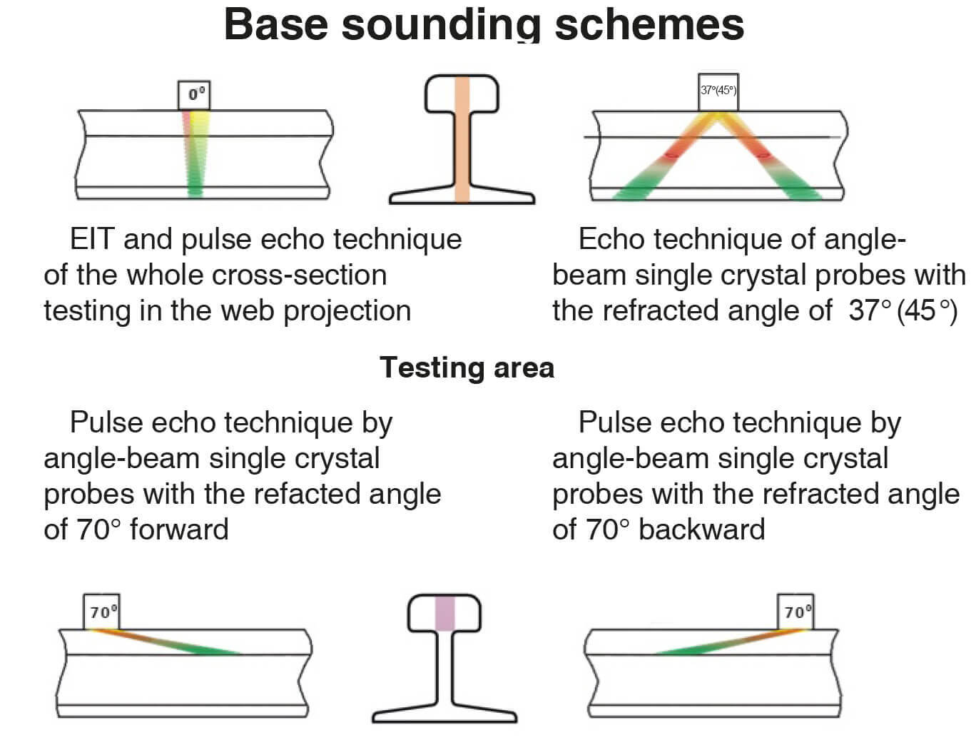
0° – is used for the horizontal delaminations along all the rail height and analysis of the acoustic coupling (by the bottom echo-signal level)
70° – for the transverse cracks detection in the rail head, the forward and backward probes are used. In some modifications of the search system three piezoelectric elements are used (either separately or in one case) thus ensuring the testing of all the rail head width.
35° (37°, 45°) – used for sounding of the rail web and base, both forward and backward probes.
For vertical cracks detection in the rail head lateral sections, so-called «Side Looking» sounding scheme with a probe angle of 40°/55° is used.
Types of search systems
Placing of the ultrasonic probes and ultrasound input is performed mainly in two ways: «ultrasonic wheel probe» (wheel probe, ref. Figure 1) sliding probes («slides»), that are widely used in Eastern Europe (ref. Figure 2);
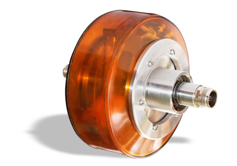
Figure 1 – Ultrasonic Wheel Search System
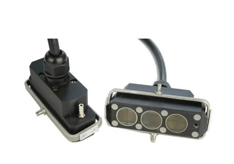
Figure 2 – Acoustic units of the Sliding Search System
Advantages and disadvantages of the ultrasound input systems
Sliding system
For sliding systems that are used on high-speed test means, first of all, it is necessary to provide the stable acoustic coupling, which is assured both by the system of automatic rail surface tracing (mechanical part), and by the system of the preliminary rail watering, and by the system of the couplant feeding directly to the probes. Watering and cleaning of a rail is provided by water jet under the high pressure (up to 100 bar).
The couplant is supplied to the probes (acoustic units) under a specific pressure. In some nondestructive testing devices the couplant is fed in a dispersed form which allows to use it economically and increases stability of the acoustic coupling.
Thus, in order to assure stable acoustic coupling the sliding system requires a huge consumption of the couplant (water) which is one of its drawbacks.
The second drawback of the sliding system is a direct contact of the acoustic units with the rail head running surface, as a result the probe units are worn quite quickly. To avoid probe wearing so-called protection shoes are used. Protection shoes are usually made from the plexiglass or hard polyurethane and are generally expendables.
UDS2-77 - ultrasonic flaw detector for testing
the condition of one rail
Explore More Wheel search system
Wheel search system represents actually a wheel with a polyurethane tire inside which the ultrasonic probes are installed. The wheel is filled with an immersion liquid (usually ethylene glycole is used). Wheel search system with probes layout is shown in Figure 3.
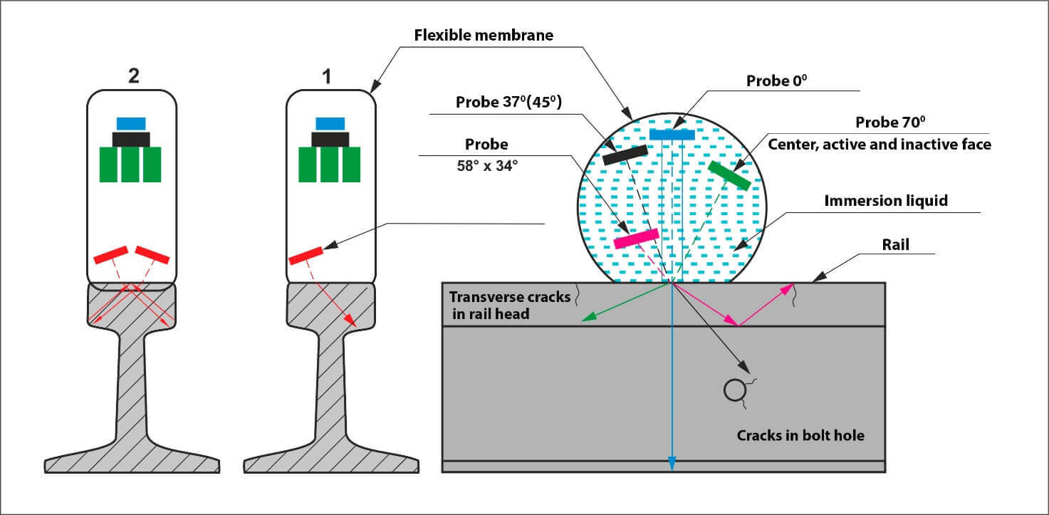
One of the most outstanding benefits of the wheel search system is its elastic tire which closely borders on the rail head running surface even if the rail head is worn. Moreover, by changing pressure rate in the ultrasonic wheel it is possible to adjust the interface spot dimensions. This ensures more stability of the acoustic coupling and, in turn, that provides a possibility to test rails at a speed of up to 40 km/h. One more advantage of the wheel search system is much lower consumption of the couplant if compared to the sliding search system. This in turn is assured by the polyurethane tire.
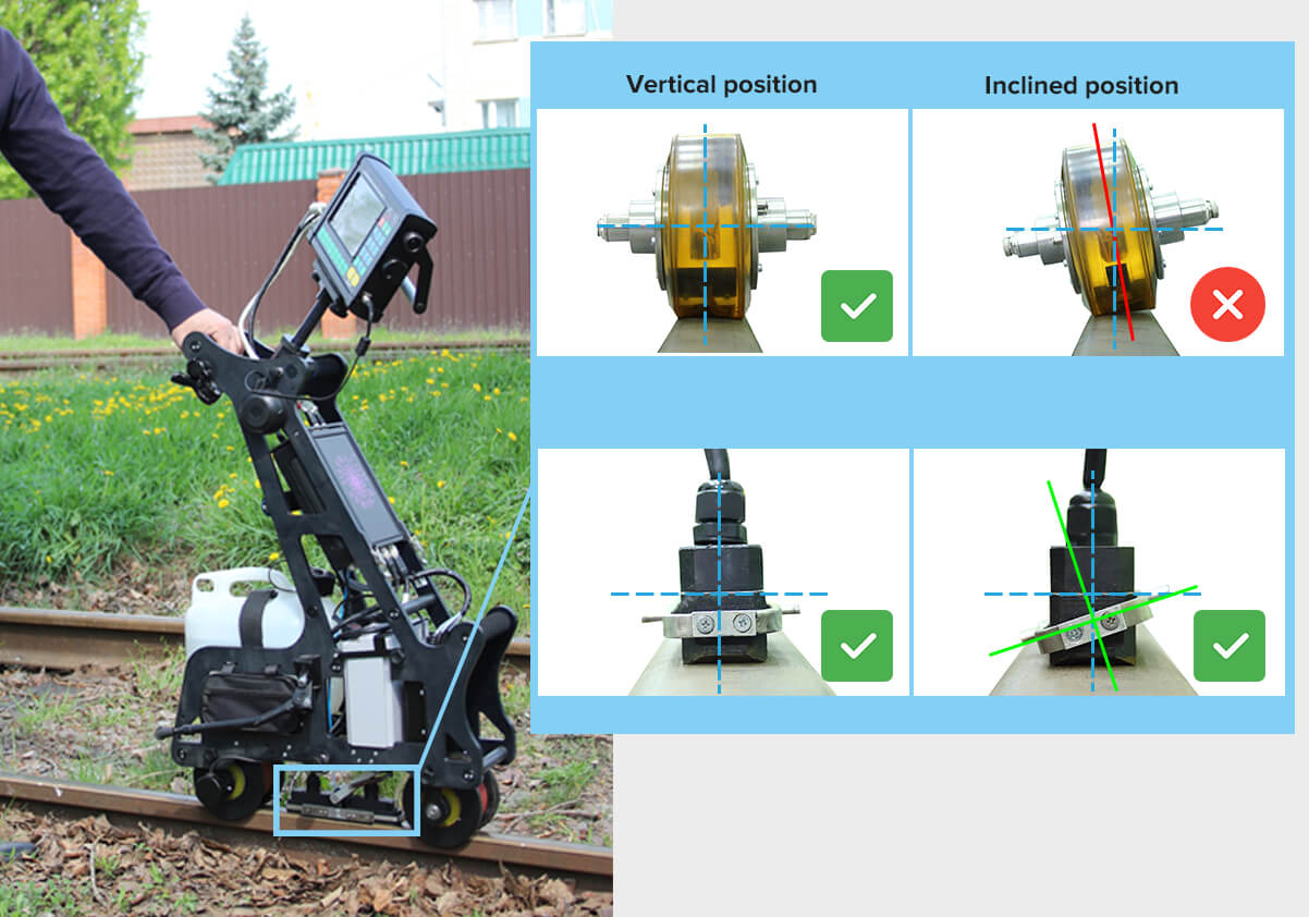
Naturally, wheel search system with all its advantages has some drawbacks. One of the essential disadvantages is the necessity of a wheel position accurate adjustment relative the rail surface in all the planes. The orientation changing for 10 in any plane can lead to the probe angle change in metal (in respective plane) for 40 and to the distortion of a sounding scheme. As a result, the operator may miss even quite large defects. That is why the use of a wheel probe in a single rail flaw detectors is not recommended. Some manufacturers ignore this limitation and install the stabilizing bar with the wheel mounted onto it. And when it leans on the second rail the convenience of using such a trolley is significantly reduced.
One more disadvantage of a wheel search system in comparison with the sliding one is that with the use of a former it is impossible to implement some of the sounding schemes, in particular those that require a fixed distance between the probes (for example, the «Tandem» scheme). Due to the geometry of the ultrasonic wheels and impossibility and failure to allocate them at a required distance between each other. Such a disadvantage result in lowering of the flaw detection quality of the plane internal defects in the rail head.
And the last but not the least, the drawback related to the test speed limitation which is conditioned by the immersion input method principle as is. In the wheel system for the ultrasonic oscillations travel from the piezoelectric element to the wheel rim some time is required which can be same or even more that travel time of the oscillations through the body of the rail. As a result the full time of flight of the ultrasound required to travel from the transmitter through the immersion liquid to the bottom surface of the rail and back to the receiver is at least two times more than in the sliding system. That also set the limitations back to the frequency of the initial pulses and to the scan speed correspondingly at which the necessary defects shall be surely detected. At a high-speed NDT means where the wheel search systems are used, the scan pitch is usually about 4 mm. Meanwhile, the test speed can reach up to 40 km\h.
In the sliding search system the ultrasonic oscillations are input directly in the test object, and the frequency of the initial pulse can be increased up to two times correspondingly, which can lead in turn either in increasing the scan speed, or in decreasing the scan pitch, for instance, at the same scan speed of 40 km/h, the scan pitch in the sliding search system will be equal to 2 mm.
Conclusion
Each of the described search systems can be used for continuous rails tetsing, each one has its pros and cons. That is why the choice of the search system types mainly depends on tradition of a railway service company. So, ОКОndtGroup produces and constantly improves both search systems types, slides, and wheels.
