Non destructive testing of welds
Visual testing
Penetrant testing
Ultrasonic testing
Pulse echo technique
Pitch catch technique
Through transmission technique
TOFD technique
Eddy current weld inspection
Magnetic particle testing
Radiographic testing
Welds are the most common type of permanent joints in all industrial sectors. There are many types of welds both in terms of welding methods (manual electric arc, automatic or semi-automatic, submerged arc, gas-shielded arc, electrical resistance welding, etc.), and in terms of joint configurations (butt, fillet, tee, lap welds). However, in most cases, irrespective of the welding method, welded joints are subject to quality testing at the end of welding. Flaw inspection is aimed at identifying various defects that lead to a weakened weld strength or poor leak tightness. Timely detection of such flaws significantly affects the determination of service life of a whole welded structure. The weld quality is particularly critical for high pressure vessels and systems, as well as for load-bearing structures.
Non-destructive testing (NDT) is the main inspection method for welded joints, since it allows maintaining the integrity and performance of a product being tested. There is a lot of NDT techniques and a variety of instrument models based on a specific technique. When selecting any of the techniques, it is necessary to take into account numerous factors such as material of the parts to be welded, weld configuration, surface condition, quality requirements, access, type and location of a potential defect (discontinuity), productivity and costs of testing. Therefore, there is no single universal NDT technique, so the quality, reliability and durability of a finished product will largely depend on the choice of the most suitable option.

Visual testing
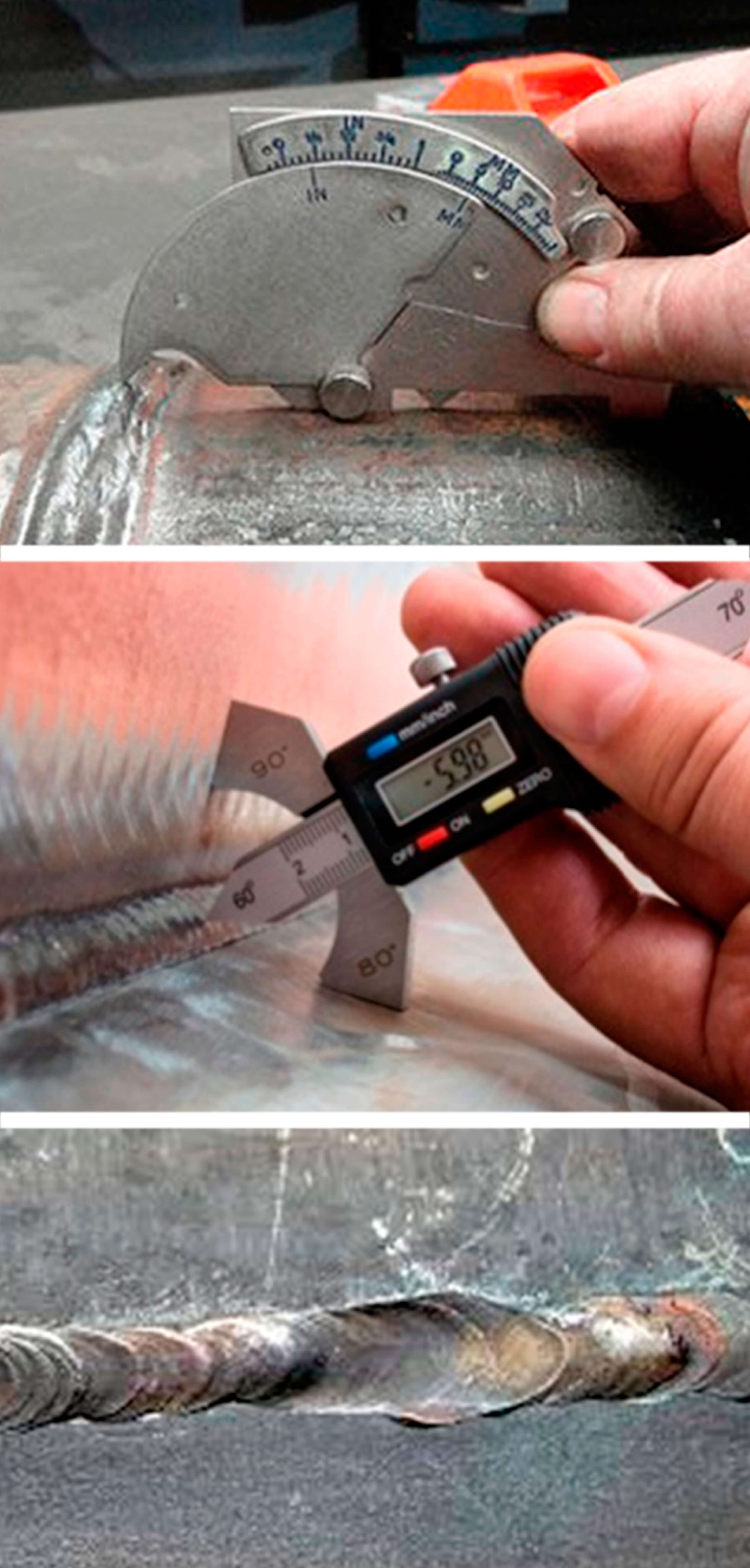
This method combines a visual inspection and measurement of the geometrical parameters of welds to check their compliance with the required values. Before testing, the welds should be cleaned from scale, slag and metal splashes. After that, the surface should be treated with alcohol, or etched using a 10% solution of nitric acid. As a tool for this type of testing, a 5 or 10-power magnifier, as well as lighting devices and measuring instruments (ruler, calipers, templates) are normally used to verify both the weld and defect sizes. Despite its apparent simplicity, this type of testing is very effective and is prior to other methods. If the flaws are detected already at this stage, the weld is considered as rejected, and further testing is not performed. An obvious disadvantage of this method is the impossibility to detect the majority of hidden defects and the subjectivity of evaluation methods, which requires a lot of experience from NDT inspector.
Penetrant testing
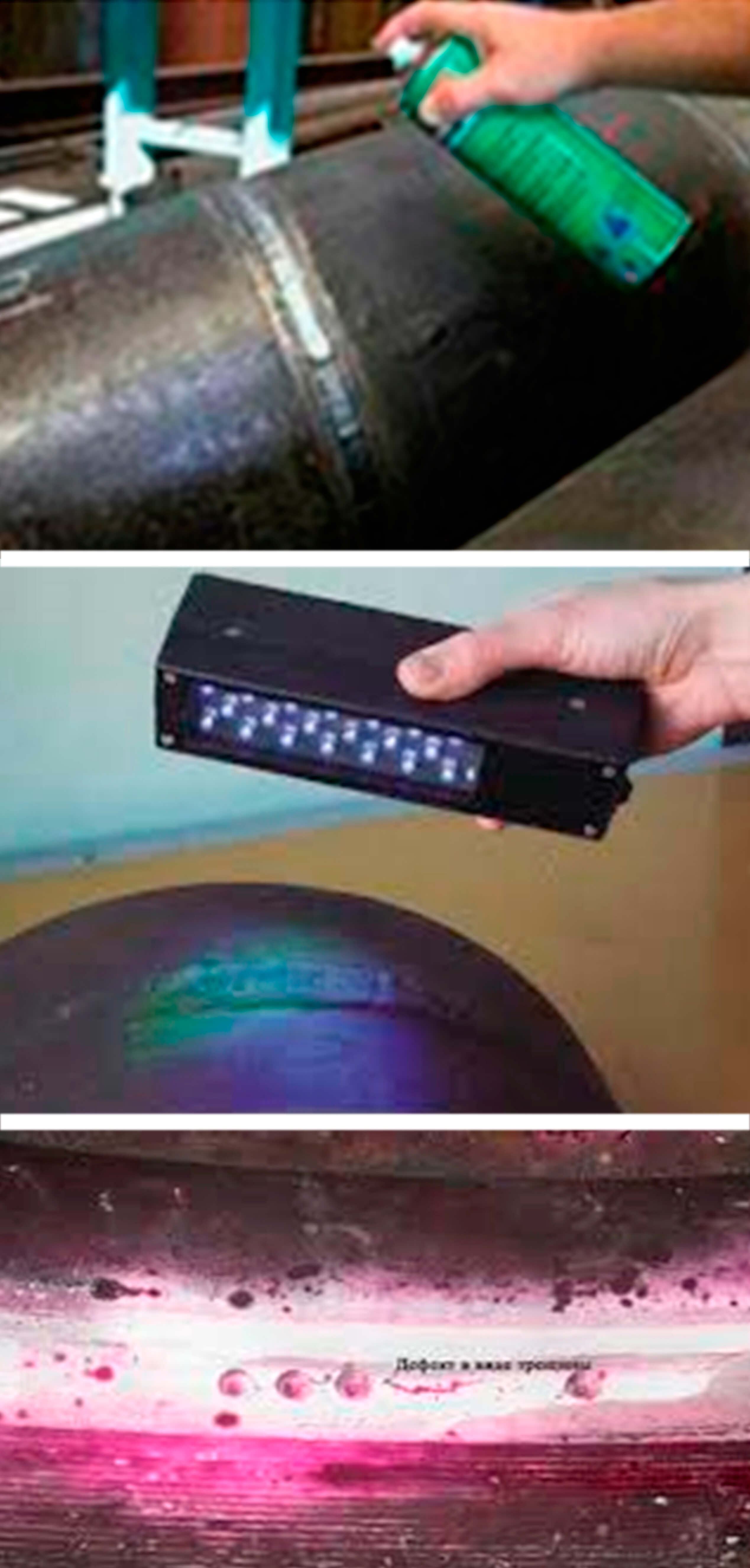
This method is based on the ability of the liquid to penetrate into and fill the smallest capillary channels that are essentially made by weld defects. Such defects include pores and cracks that break the surface of the material. The rate and depth of penetration of the liquid depends on the radius of the capillary and the wettability of the liquid. Thus, the penetrant method is very effective for detecting surface flaws. To increase its efficiency, the so-called penetrants are used which can penetrate deep into the capillary due to their small surface tension. Their bright color makes them noticeable, which facilitates the detection of a defect. A penetrant testing kit normally includes a penetrant; cleanser for thorough cleaning of the surface before testing; developer for extracting the penetrant from the defect and creating an indicator pattern on a contrast background, using which it is possible to see the size and form of the defect.
This method of testing is similar to the visual one, since it presupposes visual inspection of the weld, therefore, has the same disadvantages.
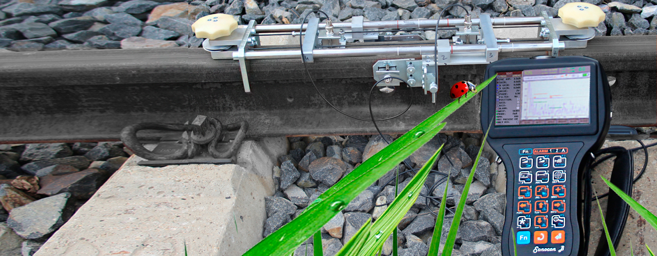
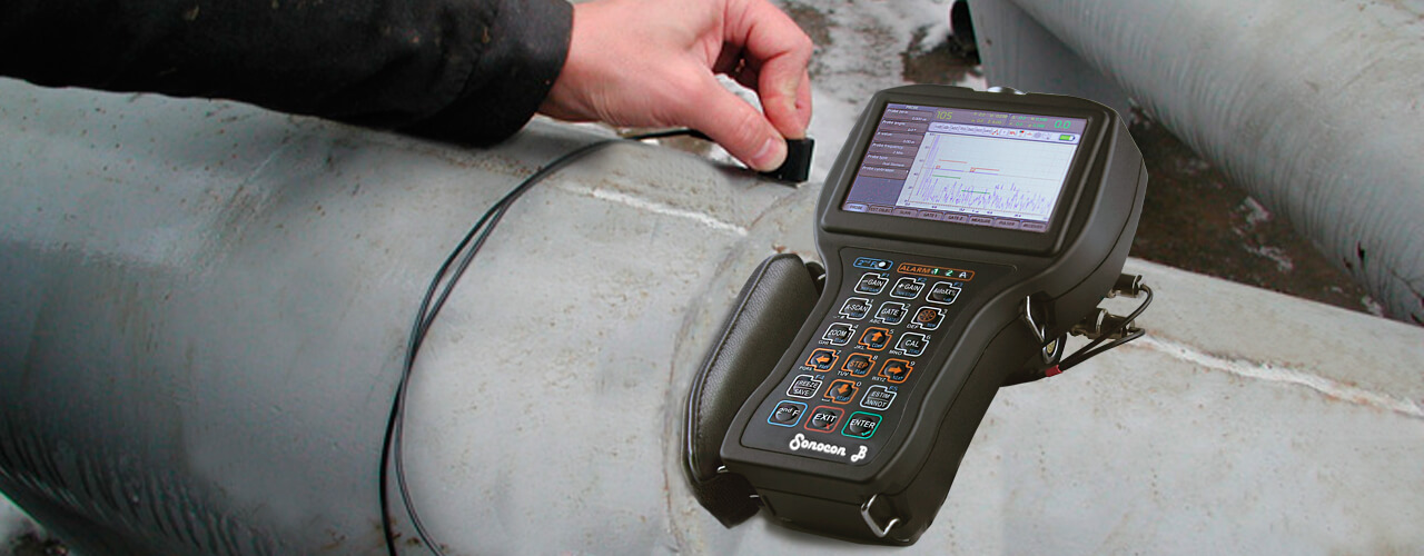
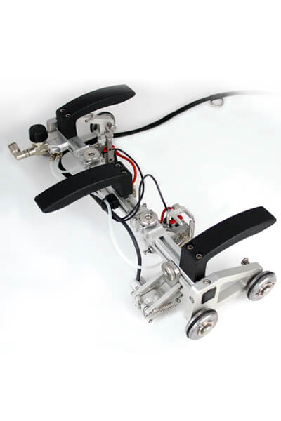
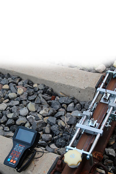
Ultrasonic testing
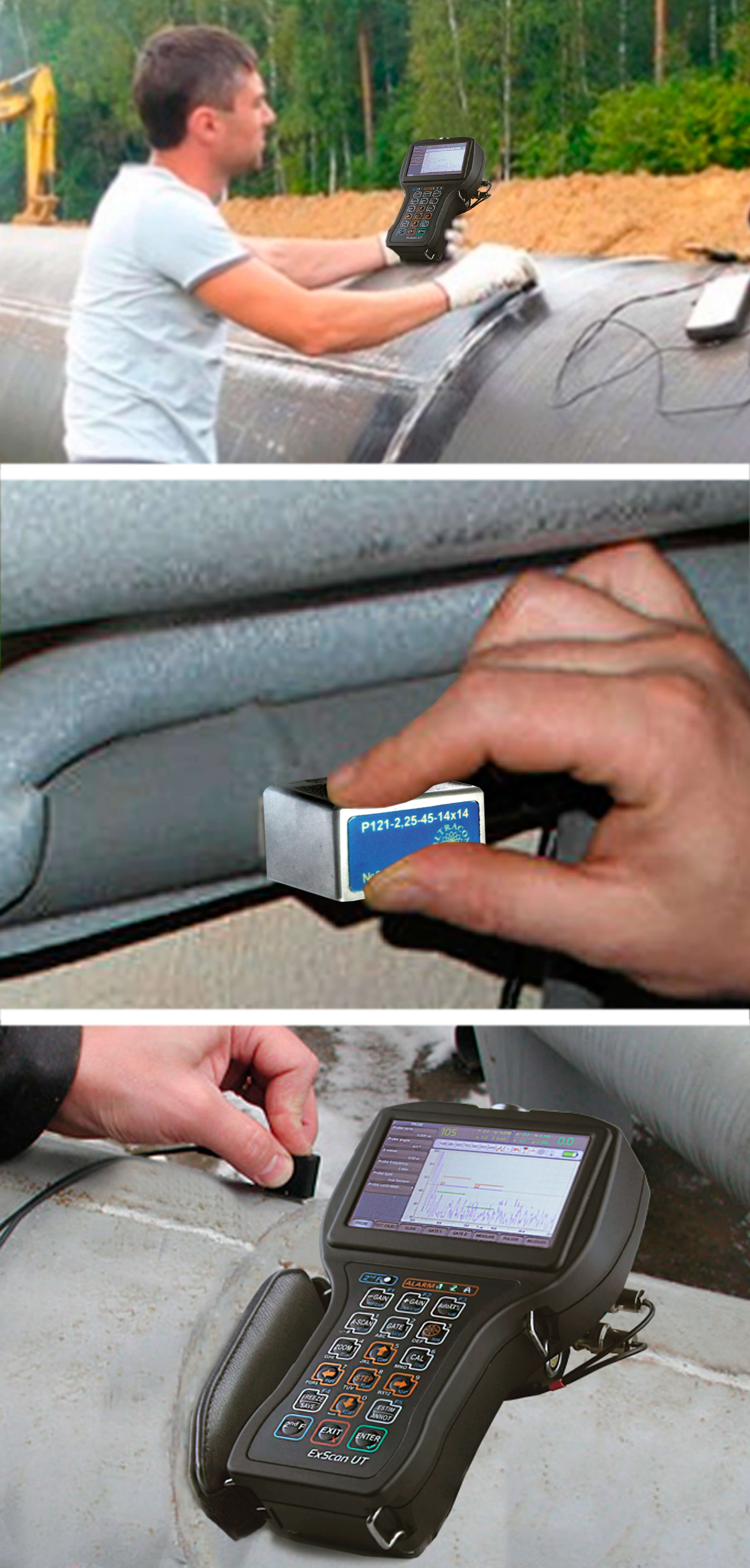
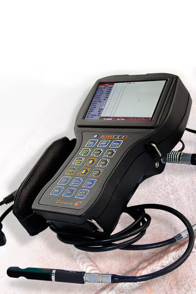
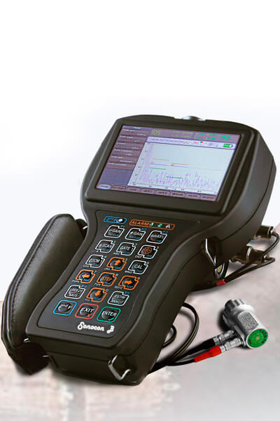
UT is one of the most common methods, because it ensures an accurate detection of hidden flaws located inside the weld. The method is based on the use of ultrasonic waves that propagate through a layer of metal and are reflected from its boundary and the boundaries of internal discontinuities. Based on the time difference between the sent and reflected signals, as well as the shape and amplitude of the reflected signals, it is possible to evaluate not only the metal thickness, but also the defects encountered on the sound path. An instrument that is used for ultrasonic testing is called ‘flaw detector’. The flaw detector utilizes special-purpose transducers (transmitters / receivers of ultrasonic signal), which allow implementing the echo pulse, pitch catch and through transmission techniques.
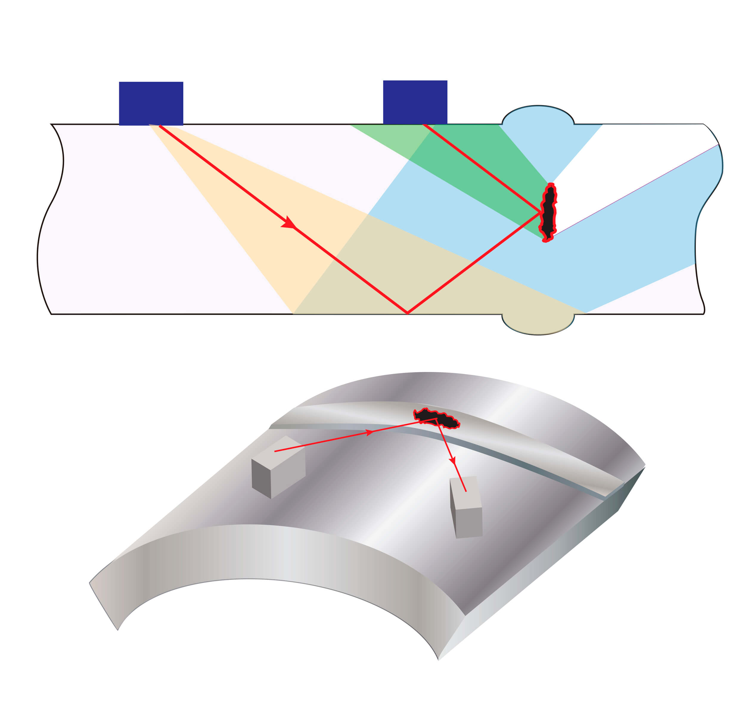
Pulse echo technique
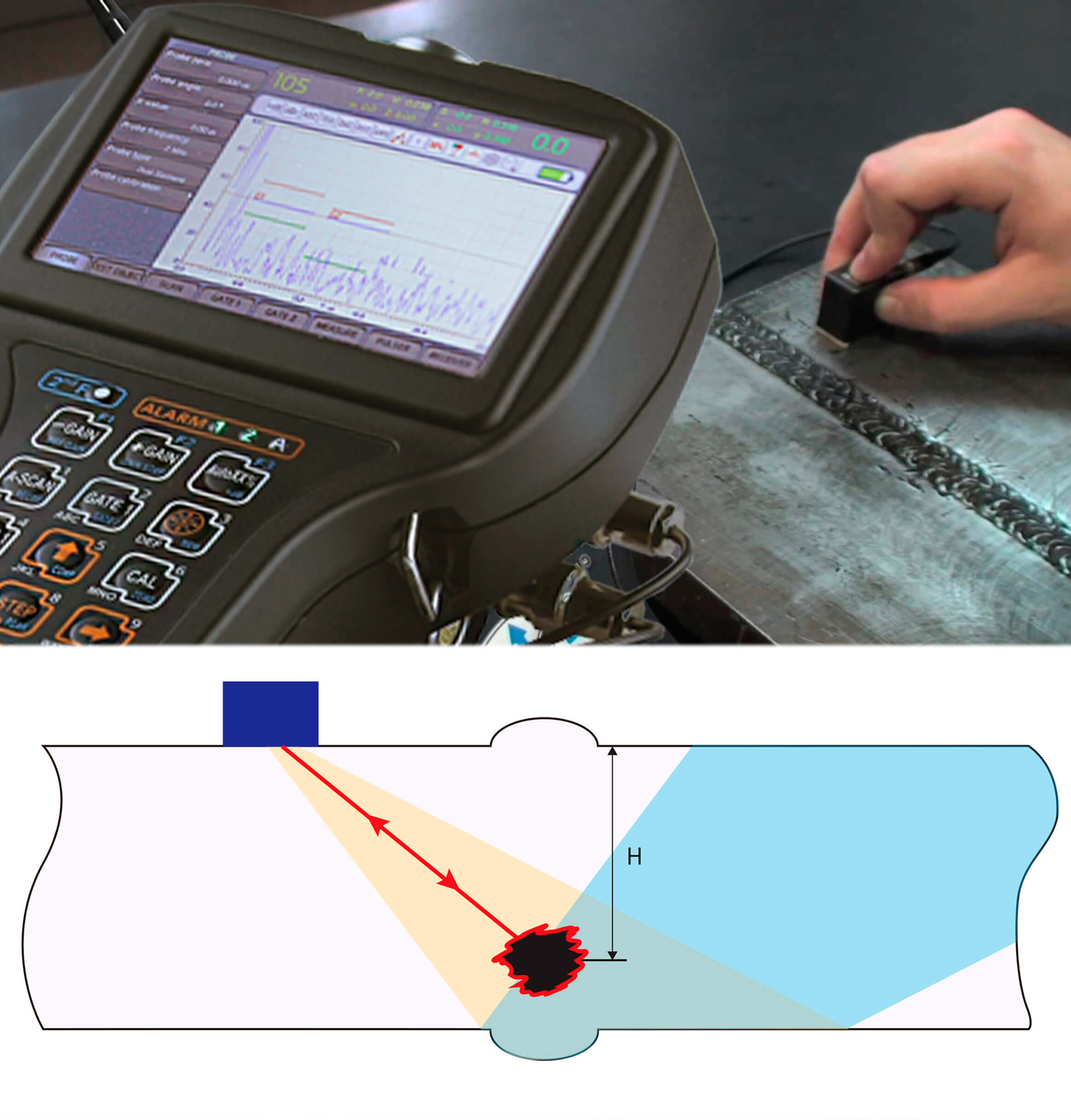
With the pulse echo technique, the transducer sends a probing signal to a test object and receives echo signals reflected from defects, as well as from design features of the product. Based on the time of the signal arrival, it is possible to spot the location of the defects, and based on the signal amplitude - the size of the defects. The disadvantage of this technique is the need for the defect to have a reflecting surface perpendicular to the ultrasonic beam, or be located near the surface of the product. For example, the pulse echo technique does not allow detecting planar defects (cracks and lack of fusion) that are not located close to the surface of the product under test.
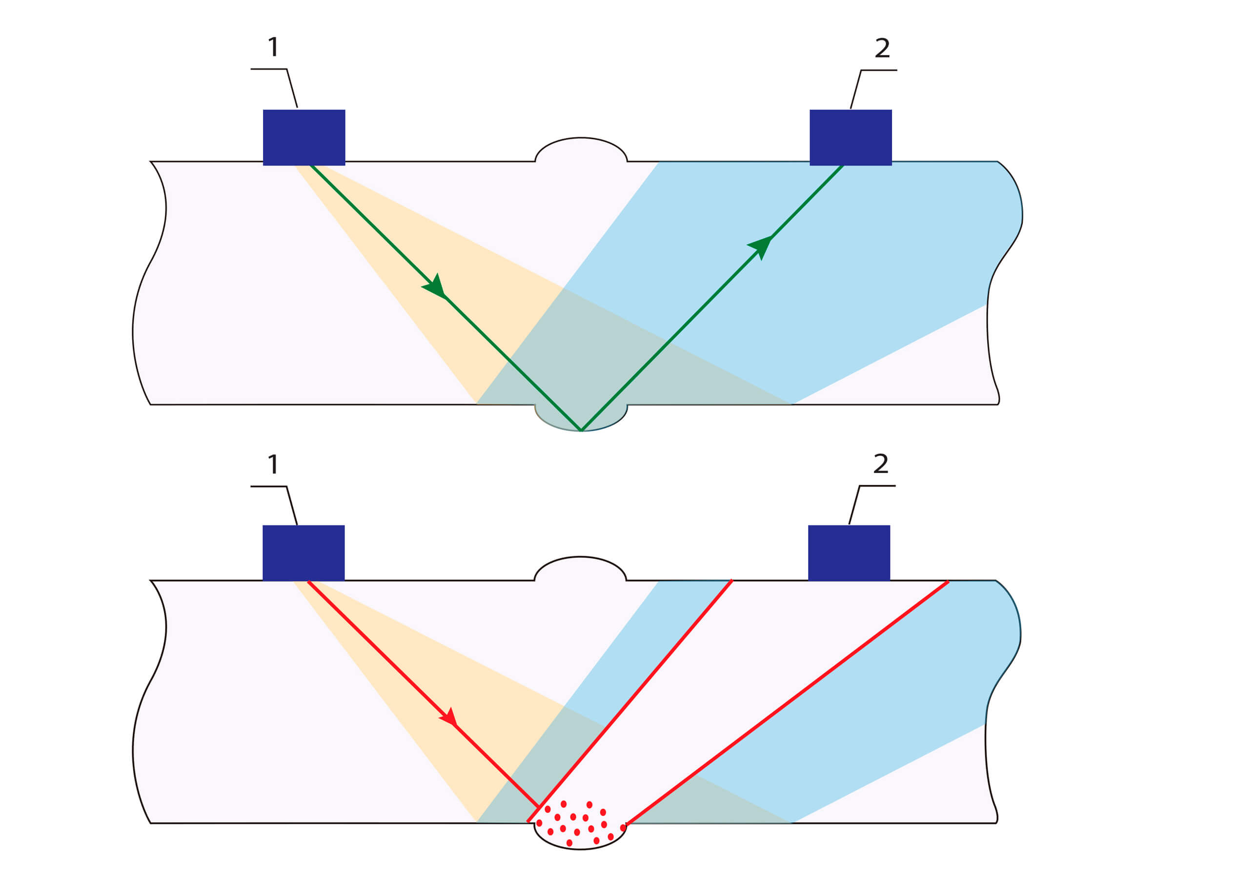
Pitch catch technique
The pulse echo technique does not allow detecting planar defects (cracks and lack of fusion) that are not located close to the surface of the product under test. The pitch catch techniques, Duet and Tandem, are used to recognize the above mentioned flaws. This is achieved with a pair of transducers installed so that the signal emitted by the first transducer is returned to the second transducer after reflection from the planar defect.
Through transmission technique
However, even the pitch catch mode does not guarantee the detection of all differently-directed flaws. For this purpose, the through transmission technique is used, with the transducers placed on both sides of the weld so that the signal reflected from the back surface comes to the receiver. Sufficiently large defects of almost any orientation crossing the ultrasonic beam shade the above signal, which evidences their detection. But, unfortunately, this technique does not provide exact information about the location (coordinates) of detected flaws. To obtain accurate readings from the ultrasonic flaw detector, it is necessary to make preliminary settings with the help of specialized reference blocks that are usually supplied together with the instrument. The reference blocks of various types can be also purchased separately, depending on a particular application or specific NDT task.
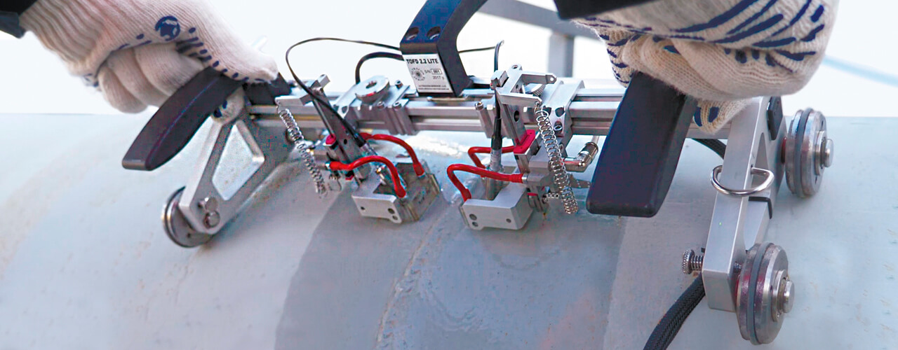
TOFD technique
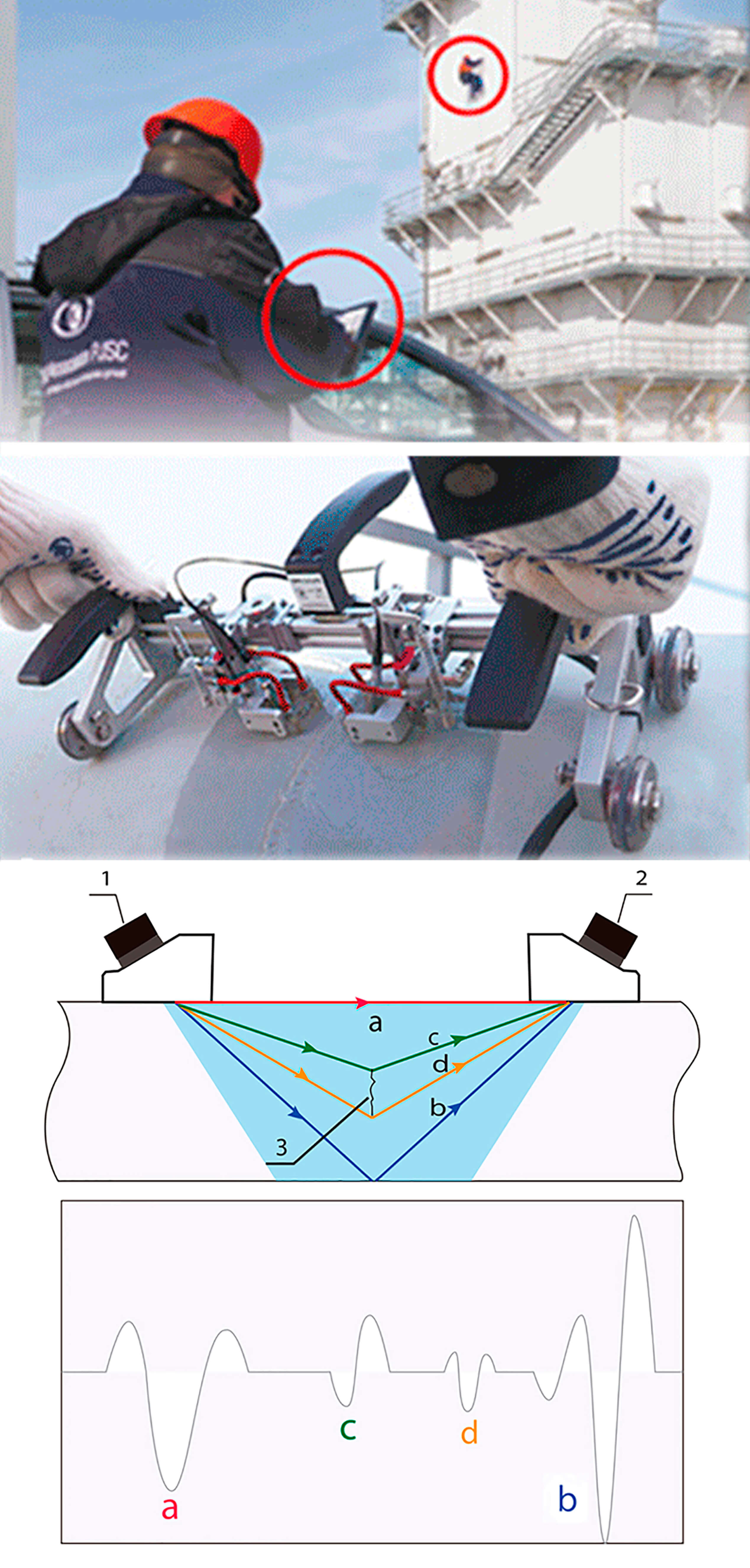
In recent decades, the ultrasonictime-of-flight-diffraction (TOFD) technique for weld examination has become increasingly widespread. The TOFD technique is based on interaction of ultrasonic waves with the edges of discontinuities. This interaction leads to generating diffraction waves with a wide range of angles. The detection of diffraction waves enables to establish the presence of discontinuity. The transmission time of reported signals is a measure of estimating the discontinuity height, thereby allowing to measure the discontinuity size which is always determined by the diffraction signal transmission time. The signal amplitude is not used for size measurement. Both longitudinal and shear waves are generated and applied in this case. The main information characteristic is the arrival time of the signal. The TOFD technique has a number of benefits as compared to conventional manual ultrasonic testing:
- Several-times higher productivity;
- Low sensitivity to the orientation of defects;
- Possibility not to estimate but measure the actual sizes of planar defects;
- High degree of reportability of test results.
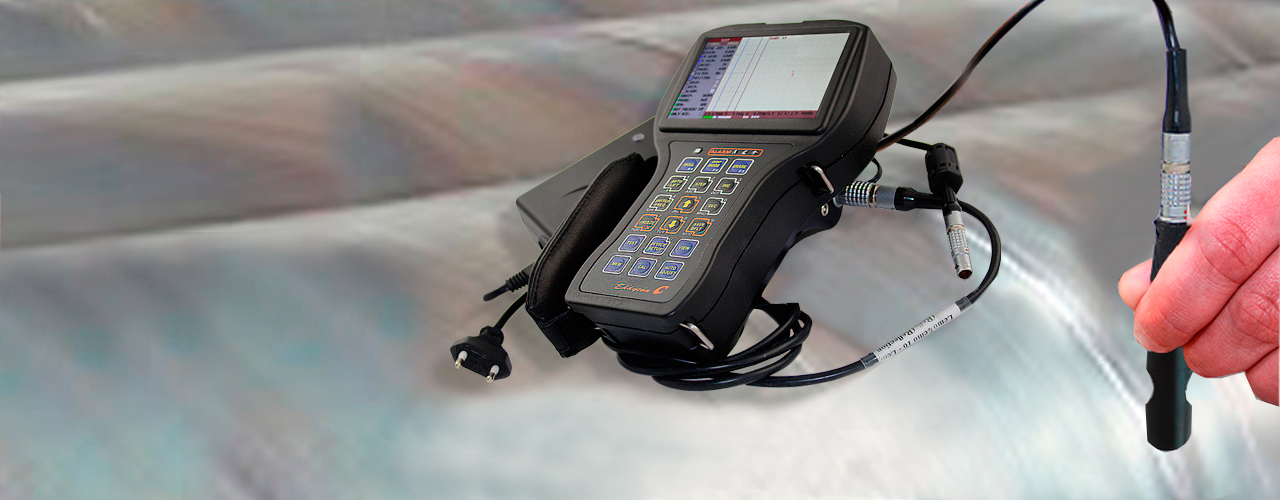
Eddy current weld inspection
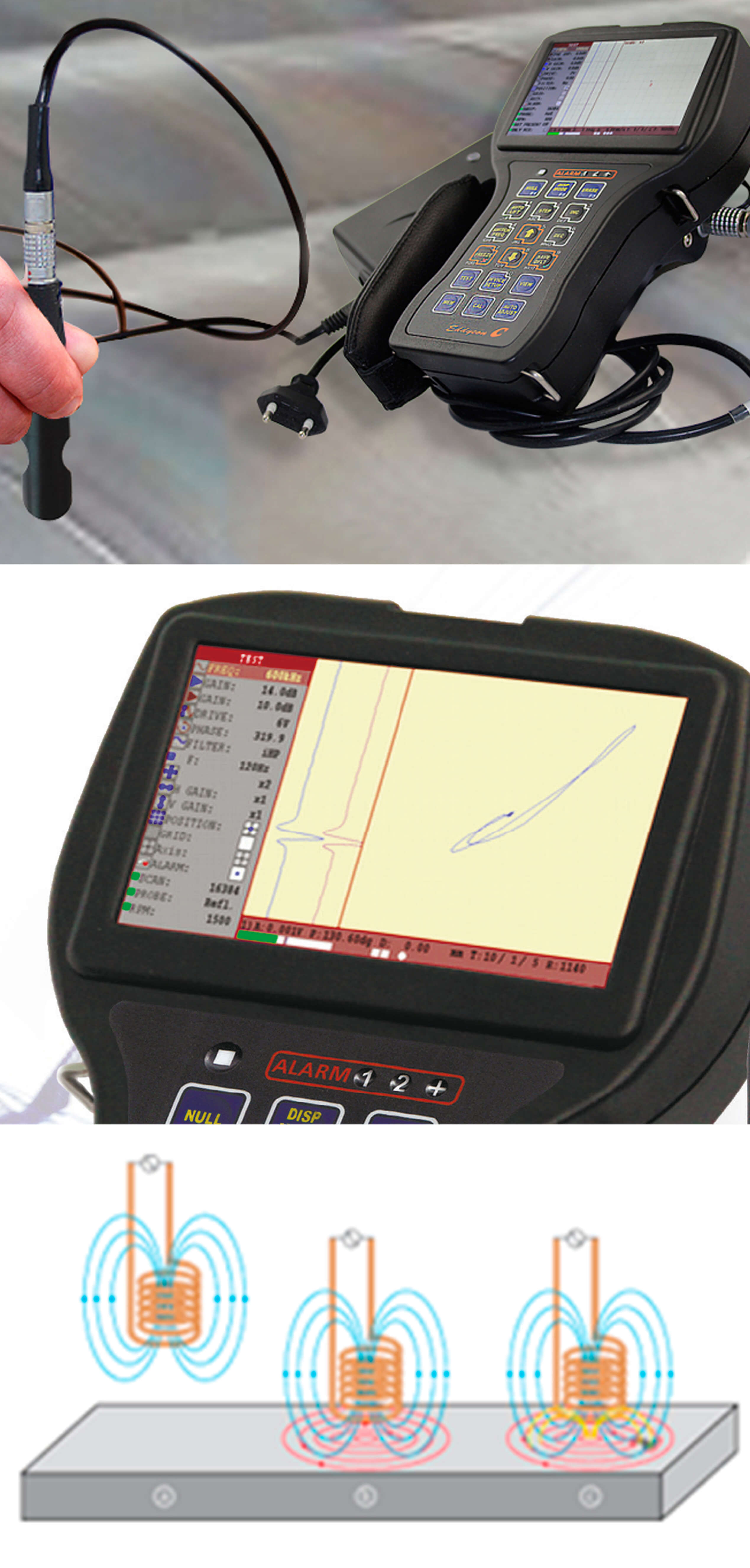
Eddy current non-destructive testing is based on the analysis of interaction of an external electromagnetic field with the electromagnetic field of eddy currents induced in a test object by this field. The operating principle of ET detectors is based on the eddy current method, which consists in the distortion of eddy currents in the local test zone, followed by recording the changes in the electromagnetic field of the eddy currents that are caused by the defect and the electrophysical properties of the test object. This method is characterized by small test depths, as it is used to detect cracks and discontinuities in the material at a depth up to 2 mm. The design and setup procedure of eddy current testers resemble the design and setup procedure of their ultrasonic counterparts, using eddy current probes and eddy current reference blocks accordingly. Obviously, the ultrasonic and eddy current testing methods complement each other, ensuring a hundred-percent reliable examination of the weld over its entire depth and extent. OKOndt GROUP manufactures a series of eddy current flaw detectors for non-destructive testing of welds.
Magnetic particle testing
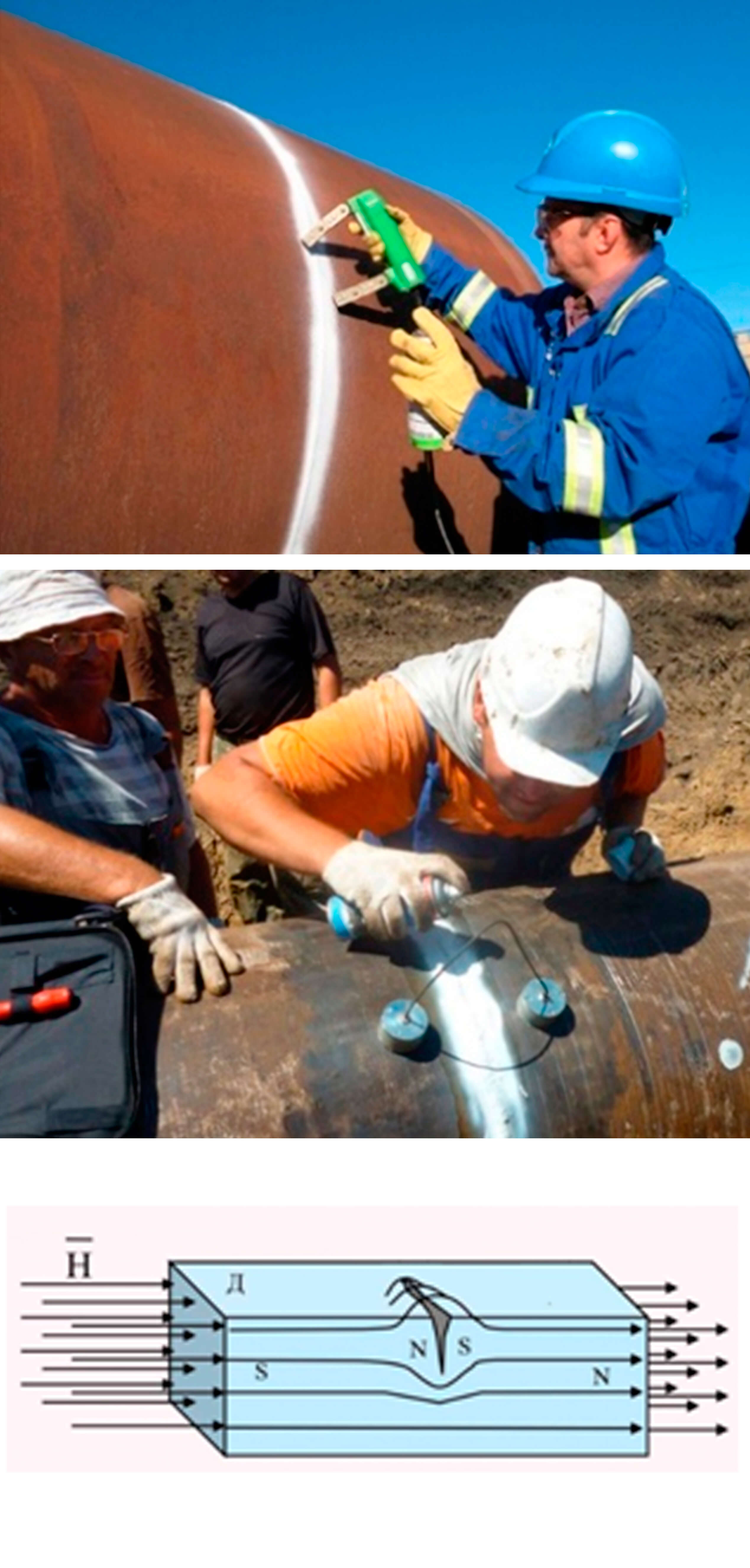
Magnetic particle inspection is a method of non-destructive testing based on the phenomenon of attraction of magnetic powder particles by magnetic scattering fluxes that arise over defects in magnetized control objects.
The magnetic particle method is designed to detect surface and subsurface discontinuities such as hair, cracks of various origin, non-melting of welded joints, floken, sunsets, tears, etc. The Magnetic Particle Flaw Detector allows you to control various shapes, welds, internal surfaces of the holes by magnetizing individual controlled areas or the product as a whole with a circular or longitudinal field created by a set of magnetizing devices powered by pulsed or direct current or by using permanent magnets.
Radiographic testing
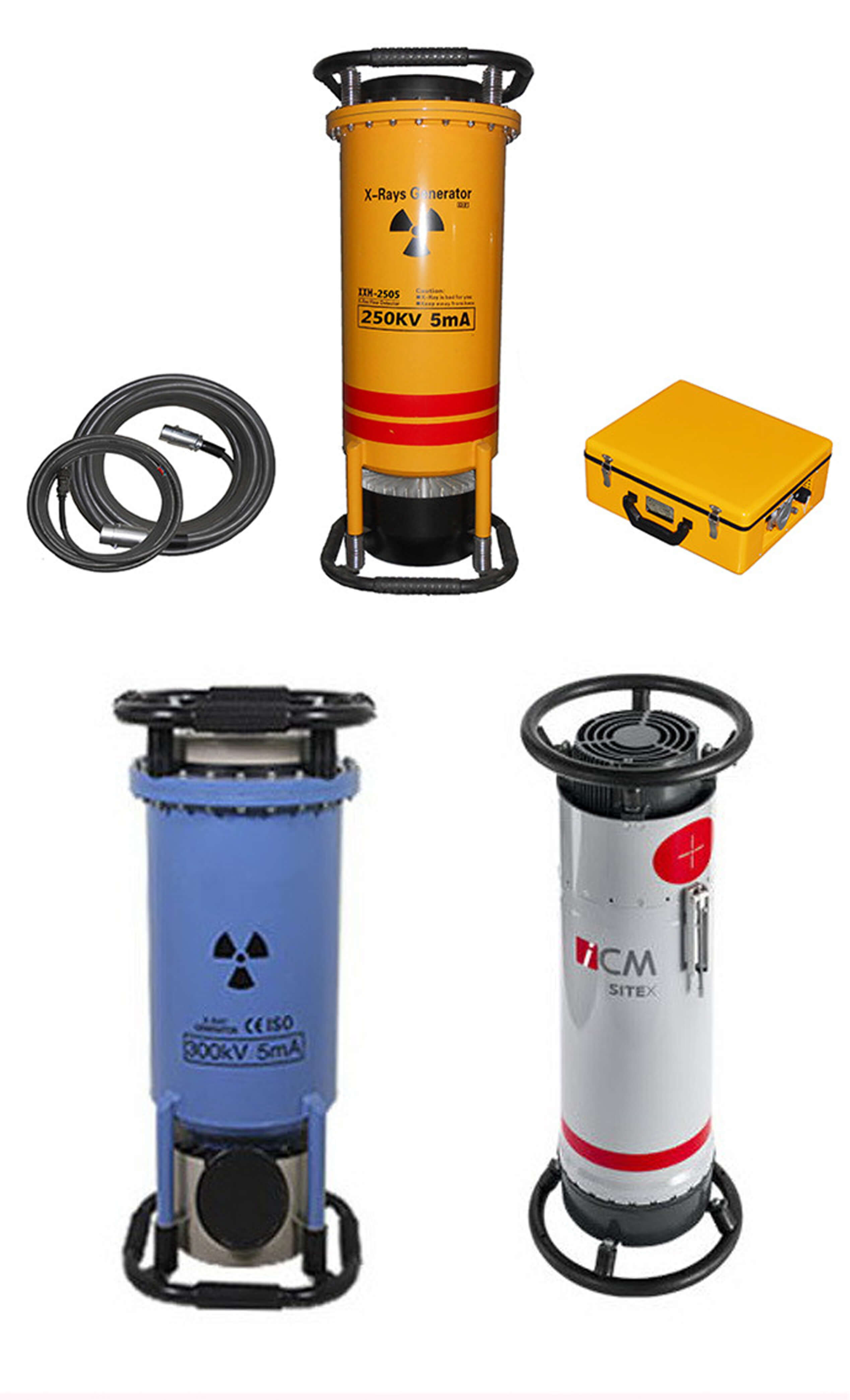
Radiography is described here only with the aim to provide a complete picture of NDT methods that are used for welds examination. Although this method is quite rigorous, its application is rather limited because it is associated with the use of gamma rays and X-rays with high permeation power, which allows them to pass through the metal, whilst the defects are recorded on the film. This increases danger to human health. In addition, instruments of this type are quite expensive. So, this is a very specific testing method that requires the use of appropriate personal protection equipment, as well as the creation of laboratory conditions for testing. Thus, we have considered the main methods of non-destructive testing of welds. It is obvious that the combined use of ultrasonic, eddy current and magnetic particle inspections ensures the most accurate test results and the safe test conditions.