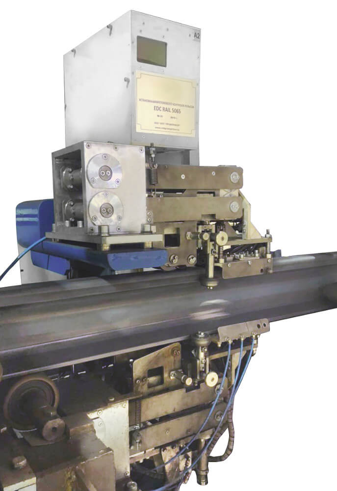


EDC RAIL 5065 Eddy-Current Testing Machine is designed for automated non-destructive testing of railway rails by eddy-current method in the course of their manufacturing. The presence of surface defects such as surface cracks of the rail heads, rail head radius transitions and sides and railway rails base of 49E1 (S49), 60E1 (UIC60) types is tested according to DIN EN 13674-1-2017.
Optionally, the Machine can include some equipment for testing of the rail head radius transitions and sides according to the requirements of DIN EN 13674-1-2017.
The Machine consists of structurally stand-alone parts installed in the manufacturing process line:
- The eddy-current rail head and rail base inspection module (hereinafter in the text - Eddy-Current Module №1);
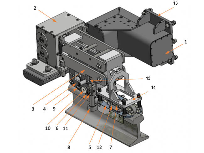
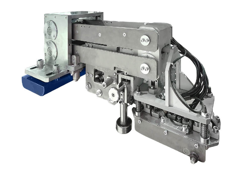
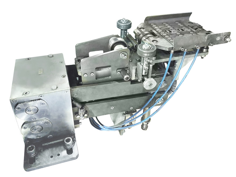
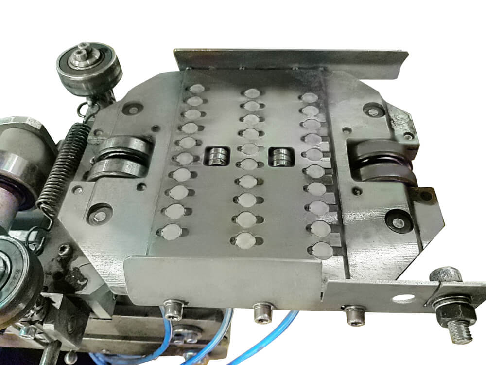
1 – bearing bracket; 2 - body; 3 - mechanism of vertical plane-parallel motion; 4 - horizontal plane-parallel motion mechanism; 5 - system of sensor units; 6 - support roller; 7 - matrix with eddy-current transducers (ECT); 8 - side rollers; 9 - locking lever; 10 - screw fly wheel; 11 - lock nut-screw; 12 - screw; 13 - base plate of the bearing bracket; 14 - plate for the matrix fixing with eddy-current transducer (ECT); 15 - fly wheel locking screw
Figure 1 – Rail head Eddy-Current Testing scanner
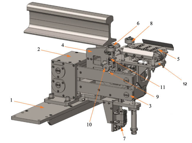
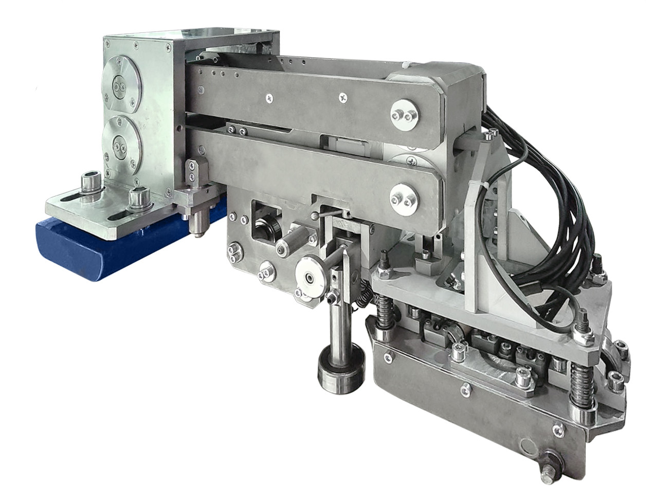
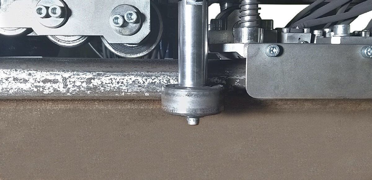
1 – bearing bracket; 2 - body; 3 - vertical plane-parallel motion mechanism; 4 - horizontal plane-parallel motion mechanism; 5 - sensors unit; 6 - support roller; 7 - pneumatic cylinder; 8 - side rollers; 9 - fly wheel locking screw; 10 - screw fly wheel; 11 - lock nut-screw; 12 - plate for fixing the matrix with ECT
Figure 2 – Eddy-Current Testing Scanner of the rail base
- EC scanner of the rail head radius transitions and sides (hereinafter in the text - Eddy-Current Module № 2);
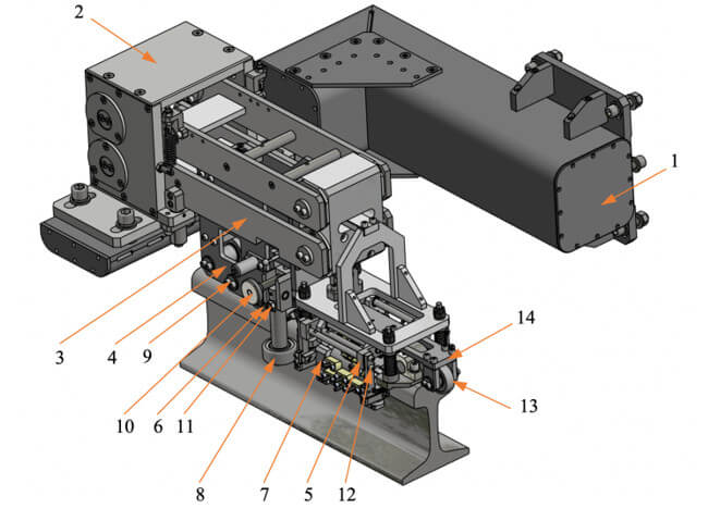
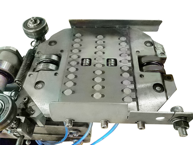
1 – bearing bracket; 2 - body; 3 - vertical plane-parallel motion mechanism; 4 - horizontal plane-parallel motion mechanism; 5 - sensors unit; 6 - support roller; 7 - matrix with EC probes; 8 - side rollers; 9 - locking lever; 10 - screw fly wheel ; 11 - lock nut-screw; 12 - screw; 13 - roller; 14 - lever
Figure 3 – EC scanner of the rail head radius transitions and sides
Advantages and main functions of the system:
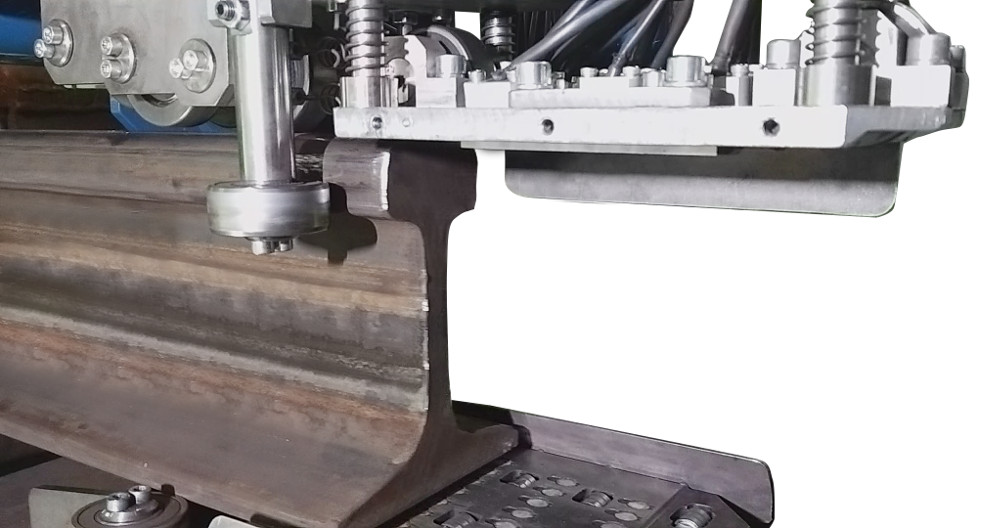
- Eddy-current module No. 1 provides for testing of the rail base except for 5 mm near-edge parts, testing of the rails head in the area of running surface within ± 24 mm from the rail vertical axis.
- Eddy-Current Module No. 2 provides for testing of the rails head in the areas with upper radius transitions (the testing area starts at a distance of ± 24 mm from the rail vertical axis) and side surfaces (the testing area finishes at the interface point of the rail head side edge with the lower radius).
- The Machine, fully assembled and equipped, covers 100% of the rails surface testing area according to DIN EN 13674-1-2017, except for the uncontrolled areas at the ends: uncontrolled area at the front end of the rail (in the direction of rail travel) is 200 mm and uncontrolled area at the rear end of the rail (in the direction of rail travel) is 100 mm.
- The rails of type 49E1 (S49), 60E1 (UIC60) manufactured in accordance with DIN EN 13674-1-2017 are subject for testing with the Machine.
- The length of the tested rails is 25 m.
- The Machine displays defective rail cross-sections in real-time display mode, with the information displayed on the monitor, and paint marking of defective rail cross-sections is performed in real-time display mode. The paint marking accuracy is not worse than ± 100 mm.