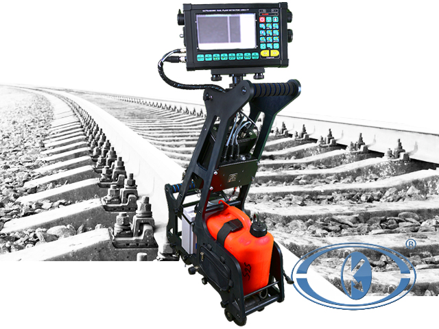

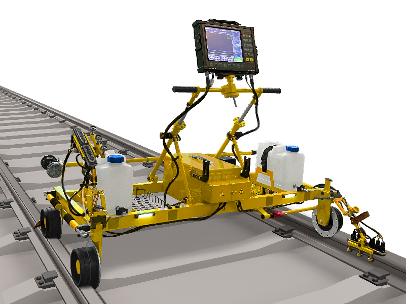


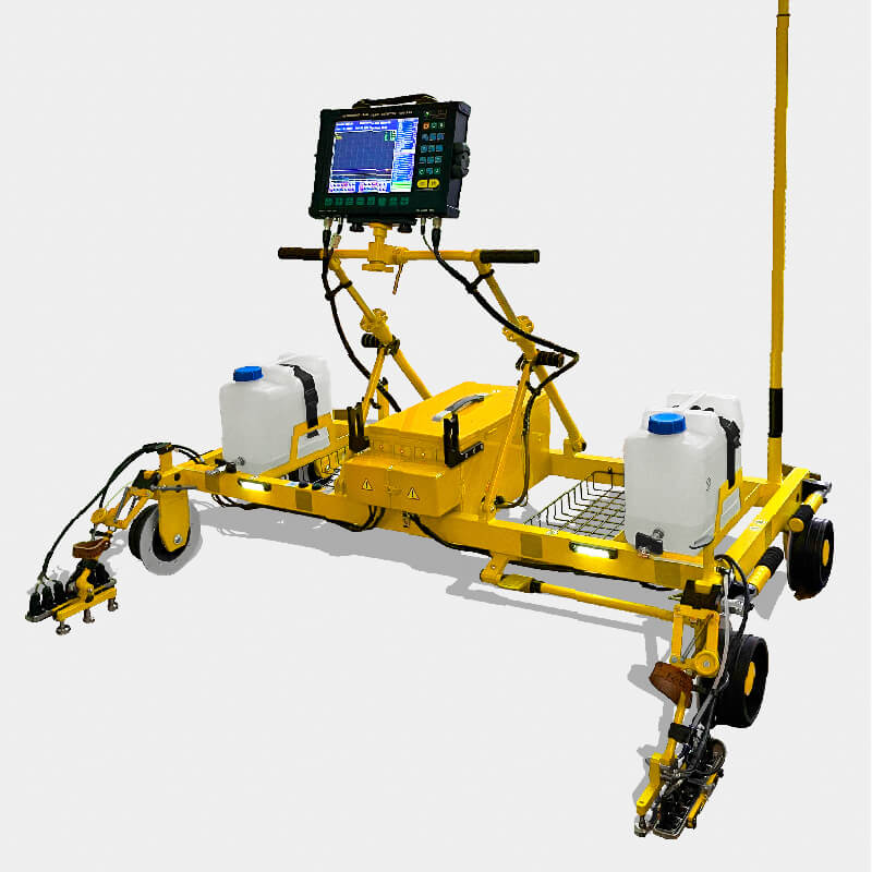
UDS2-73 Purpose
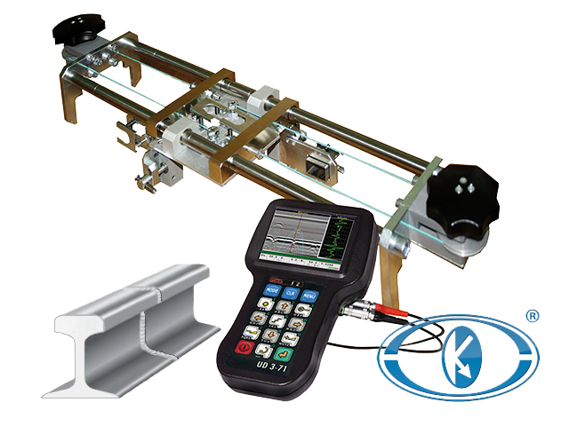
The flaw detector is intended for defects detection in both rails along the running surface and rail cross-section, except for the rail base blades using flaw detection trolley during complete testing, and for the confirmatory testing of separate rail cross-sections and welded joints by means of manual probes.
Flaw detector advantages
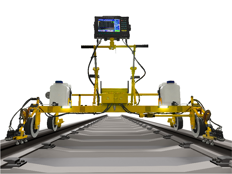
- Rail complete ensounding (except for the base blades), due to the flaw detector multi-channeling;
- built-in standard setups for channels operation;
- defining the traveled distance and motion speed during the complete testing;
- real-time testing results display in B-scan mode (by 4 channels);
- ensounding and saving the information in every millimeter of traveled distance via all channels is provided in the flaw detector;
- testing results record at different sensitivity levels;
- registration of all testing results and advanced capabilities of data analysis;
- the flaw detector with the base sounding scheme application allows to detect all types of fatal defects, appearing while rail track operation.
Flaw detector distinctive features
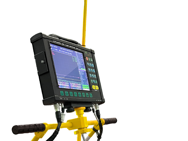
- Large color high-contrast TFT display;
- synchronization by encoder;
- information display forms: А-scan, B-scan;
- number of channels for complete testing: 28;
- number of channels for manual testing: 3;
- techniques and areas of rail head testing:
- echo technique by angle-beam probe for the testing of field and gage side of railhead along and against the movement;
- echo technique by angle-beam probe for the testing of central part of railhead along and against the movement;
- echo-mirror technique by angle-beam probe for the testing of central part of railhead along and against the movement;
- echo-mirror technique by angle-beam probe for the testing of field and gage side along and against the movement;
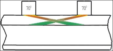
Fig. Echo techniques for railhead testing
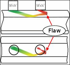
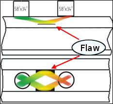
Fig. echo-mirror techniques for railhead testing
- Techniques and areas of a web testing and its projection in the base:
- echo and echo-images techniques by straight-beam single-crystal probe for detection of longitudinal horizontal cracks;
- echo techniques by angle-beam probe along and against the movement for detection of transverse cracks and testing of bolt holes;
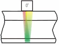
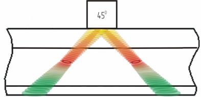
Fig. Echo techniques for the web and base testing
Flaw detector using the base sounding scheme enables to detect all types of fatal defects with the following features:
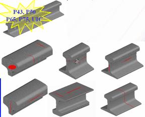
Fig. - Types of sharp-defective rails
- transverse cracks in the 2nd-category railhead, including well-developed transverse cracks with reflecting surface and also the ones developing under horizontal roll surface separations which are not detected by standard echo technique;
- longitudinal horizontal cracks in the web, even if they did not reach the rail axis in their development, and also in the head, including the ones that do not go beyond the web projection;
- longitudinal horizontal cracks located in the middle of the rail height;
- cracks from bolt holes, including the ones in early stage of their development when they do not go beyond the bolt hole projection to the roll surface;
- vertical cracks in the base and web located mainly along the rail axis;
- transverse corrosion cracks in the base located in the web projection area.
Instrument service functions
- Sound and visual alarm, modes switching with the help of "hot buttons";
- possibility of electronic registration of testing results by all channels allow to perform their reinterpretation and make complete reports;
- mode of defyning the rail type and automatic correction of setups;
- mode of bolt holes testing by special setups;
- for in-depth analysis of detected signals, except for the usual information display in the form of А-scan, the B-type sweep is used in real time by one, two, four channels (left and right rail of driving into and driving out channels) is applied;
- possibility of TCG curve (of any shape) plotting.
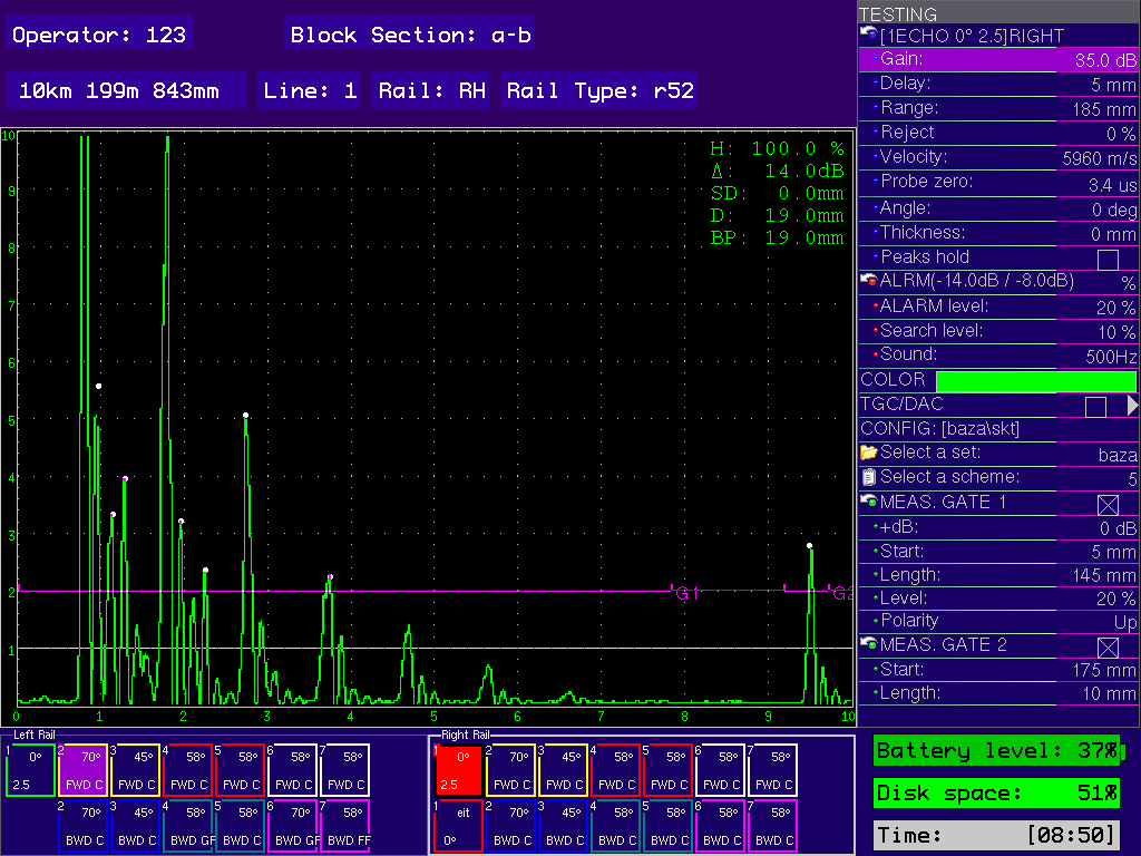
А-scan
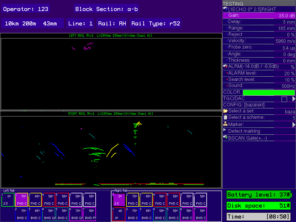
B-scan
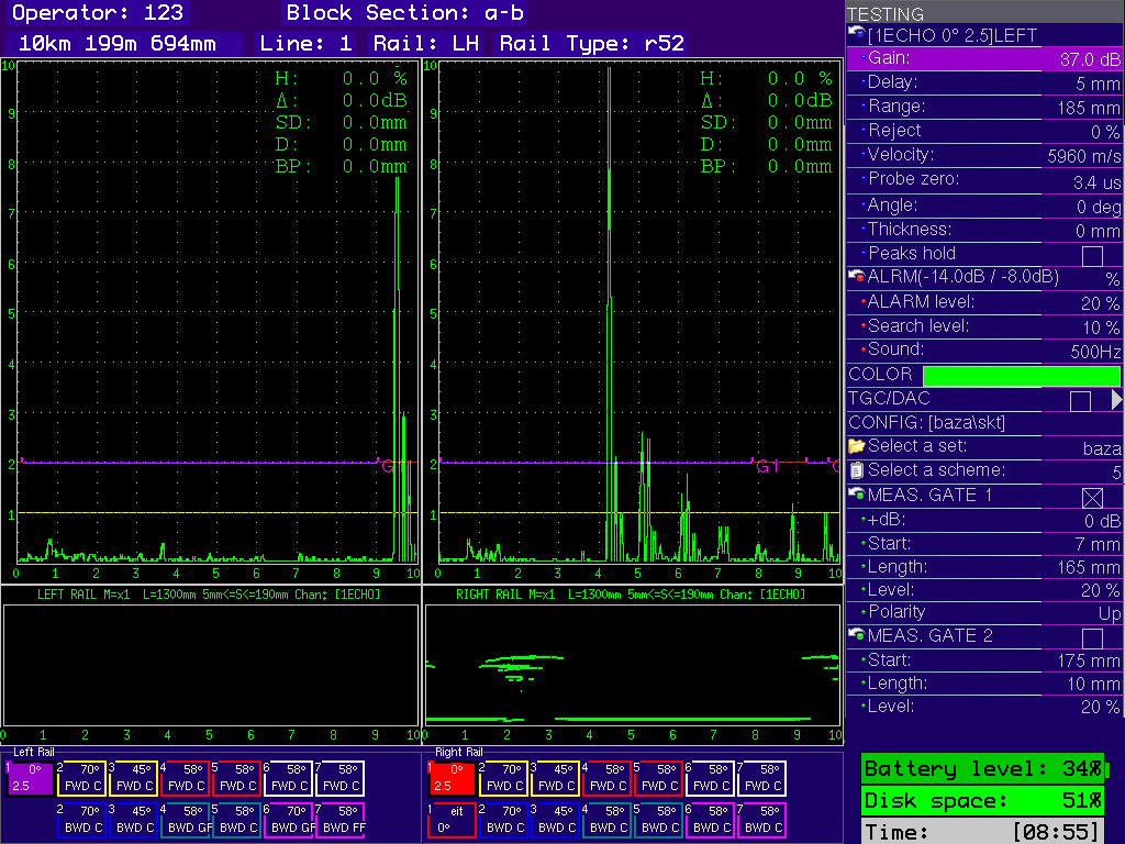
А-scan+B-scan
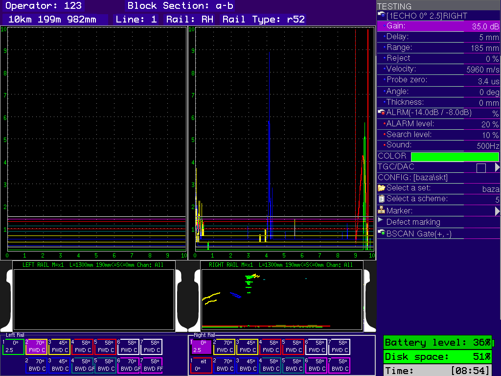
Multi А-scan+ B-scan-All
Fig. Modes of testing results display in A-scan and B-scan on the flaw detector screen
Additional software
"LuCH-Controller 1.6" is intended for viewing and analysis of testing results of UDS2-73 ultrasonic rail flaw detector and serves for interpretation carrying out and display of information on suspicious rail sections. The present program provides operation with the data stored on a personal computer.
Main advantages of program application are:
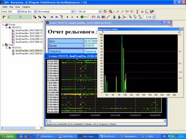
- Convenient operation with the tested sections (spans) database;
- possibility of selection of various grouping of testing channels, testing rail, rail testing area, testing technique;
- possibility of conditional dimensions measurement in B-scan mode;
- possibility of А-scan viewing by the stored data in B-scan mode;
- possibility of movement throughout the defectogram (B-scan) by means of scrolling mode or mode of fast shift to the set coordinate;
- "Position marks" mode for suspicious rail sections marking during testing results viewing;
- mode of testing results filtering by the sensitivity level from minus 6 to plus 6 dB relative to ALARM level;
- mode of viewing and generation of reports on the selected testing section.
Main specifications:
| Overall dimensions of flaw detector without a handle and with one ultrasonic unit and power unit | no more than (1040×1640×1130) mm; in transport position – no more than (900×2060×600) mm. | |
| Equipped flaw detector weight | no more than 50 kg. | |
| Keypad | English, Russian. | |
| Languages | English, Russian. | |
| Number of ultrasonic units | 4 | |
| Number of ultrasonic channels | 28 channels. | |
| Connector types | BNC, RS-19. | |
| Data storage | Flash card. | |
| Independent power source | NiMH storage battery of rated voltage 12 V and rated capacity 17 А∙h. | |
| Operation time | 10 hours. | |
| Flaw detector consumed electric power | no more than 30 V•А. | |
| Time of flaw detector operation mode setup | no more than 15 sec. | |
| Display resolution | 800×480 pixels. | |
| Screen dimensions (width, height, diagonal) | 155 mm, 95 mm, 180 mm (7.5 inches). | |
| Warranty | 1 year. | |
| Interfaces | ||
| USB | USB-A (host), USB-B (slave). | |
| Trigger O | available. | |
| Headphones | available. | |
| Encoder output | Single-coordinate encoder. | |
| Main metrological performances | ||
| The limits of admissible main absolute error of flaw detector during the measurement of depth dН and coordinates |
| |
| The limits of admissible main absolute error during the measurement of signals amplitudes ratio ∆N at the reception path input in the gain range from 20 dB to 80 dB | ∆N = ±(0.2+0.03N); ∆N ─ main absolute error during signals amplitudes ratio measurement, dB; | |
| Time instability of flaw detector reception path sensitivity | ± 0.5 dB for 8 hours of continuous operation. | |
| Protection level in operation | IP 64 | |
| Ambient temperature | from minus 400 to plus 500С. | |
| Atmospheric pressure | from 84 to 106,7 kPa. | |
Relative humidity | (93 ± 3) at a temperature 25 ºС. | |
| Flaw detector in shipping package is resistant to the influence of |
| |
| Flaw detector retains its parameters when it is influenced by electromagnetic interferences which do not exceed the following norms |
| |
| Full average flaw detector lifetime | no less than 10 years. | |
| Probability of no-failure operation | no less than 0.9 for 2 000 h. | |
| Pulser | ||
| Initial pulse type | Short pulse of negative polarity. | |
| Initial pulse frequency | One-channel mode – 250 Hz; complete mode – no more than 1000 Hz. | |
| Amplitude | 180 V | |
| Duration | 60±10 ns | |
| Rising edge duration | no more than 20 ns. | |
| Synchronization type | from an initial pulse, from an encoder. | |
| Receiver | ||
| Gain | from 0 to 100 dB with a step of 0.1, 1, 10 dB. | |
| Input signal | no more than 2 V from a peak to a peak. | |
| Input reception path resistance | no more than 300 Ω. | |
| Digital filter | 1 standard digital filter with central frequency 2.5 MHz. | |
| Rectifier | envelope. | |
| Setups mode | ||
| Measurements | mm | |
| Testing range | from 0 to 1000 mm, with a step 1, 10, 100 mm. | |
| Velocity | from 2000 m/s to 8000 m/s, with a step 1, 10, 100, 1000 m/s. | |
| Probe zero | from 0 to 60 µs, with a step 0.1, 1 µs. | |
| Range delay | from 0 to 1000 µs, with a step 1, 10, 100 µs. | |
| Probe angle | from 0 to 900, with a step 10, 100 | |
| Cycles/gates | ||
| Number of cycles | max. number of cycles 16. | |
| Cycle duration | 0.01 - 0.4 ms. | |
| Number of gates in a cycle | max. number of gates 2 for each channel. | |
| Gate fixation level | from 0 % to 100 % of vertical screen scale. | |
| ALARM | When the signal goes beyond the ALARM level, when the signal stays within the ALARM level. | |
| ALARM system | ||
| Sound ALARM system | sound – separate for each rail and combined (for a group of channels); range of pulse frequency setup of alarm system sound indicator is from 0.5 to 5 kHz, with a step 100 Hz. | |
| Light ALARM | light – separate for each rail and combined (via all ensounding channels); visual by the screen – separate for each rail and each channel. | |
| Measurements in A-scan mode | ||
| Displayed parameters | 4 measuring parameters are displayed in a status bar. | |
| ||
TCG curve | max. number of points is 14 per cycle, dynamic range 100 dB, vertical setup step 1 dB, horizontal – 2 mm. | |
| Measurements in B-scan mode | ||
| "Raw" B-scan |
| |