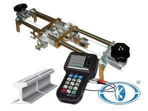


UDS2-77 purpose
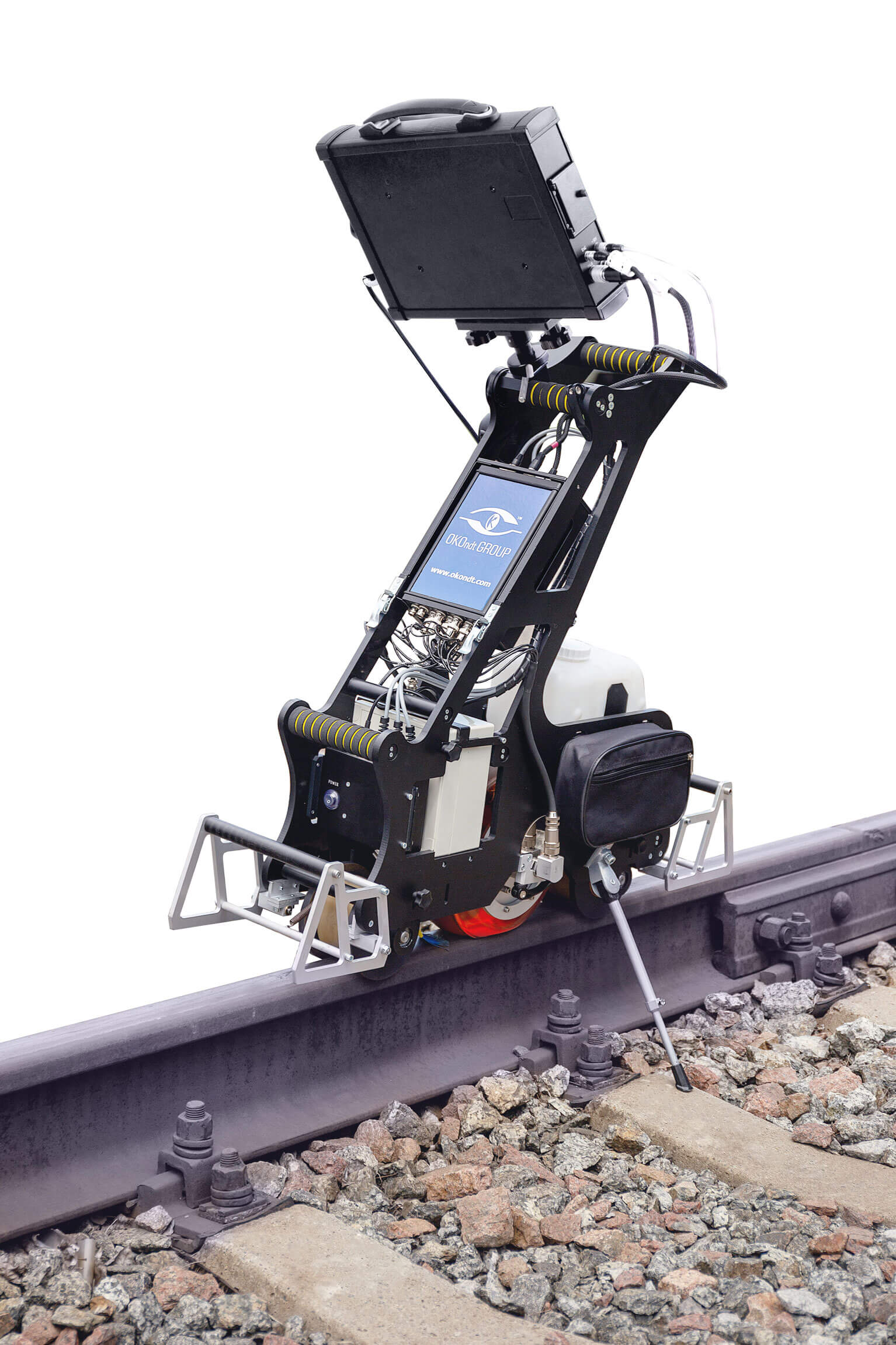
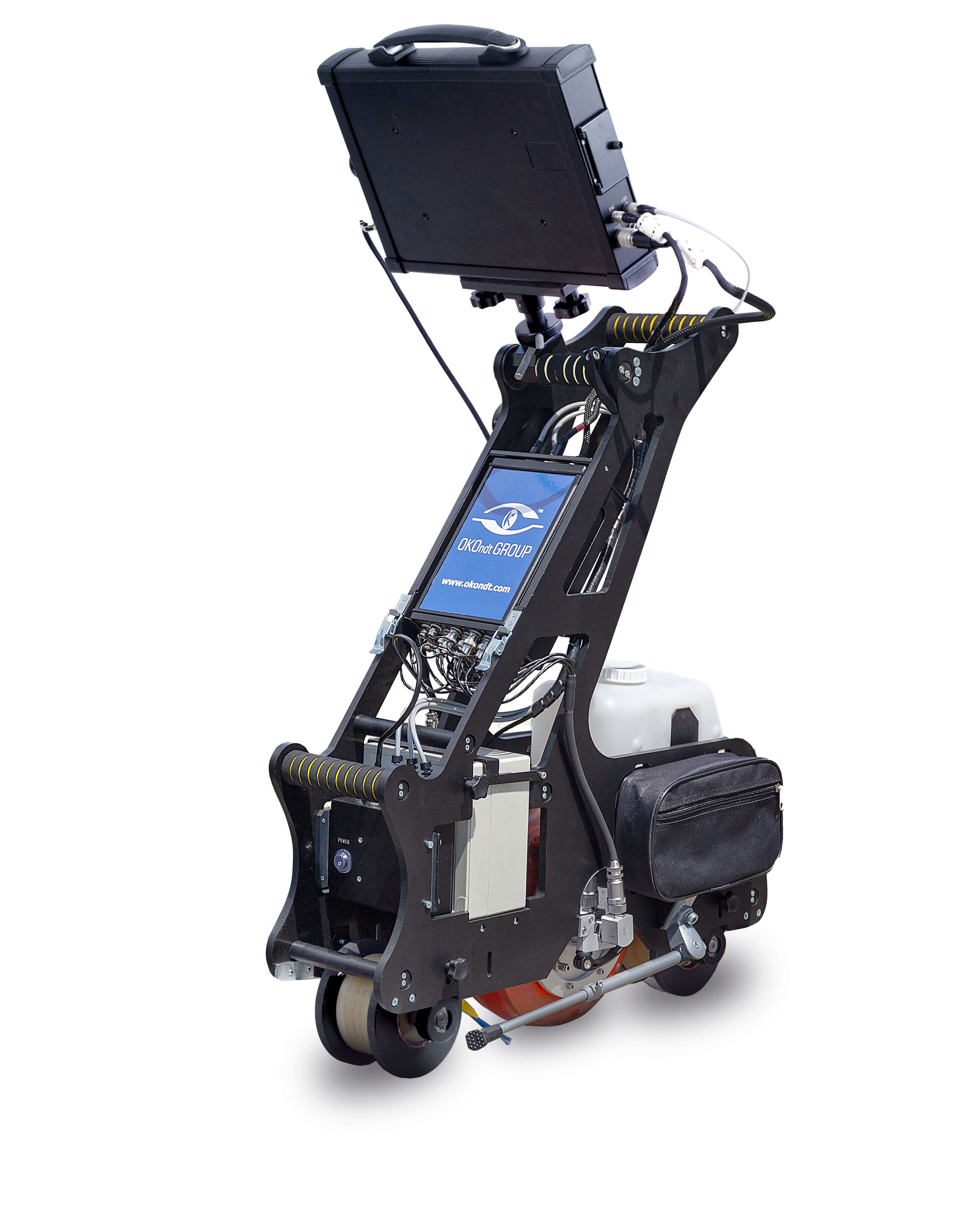
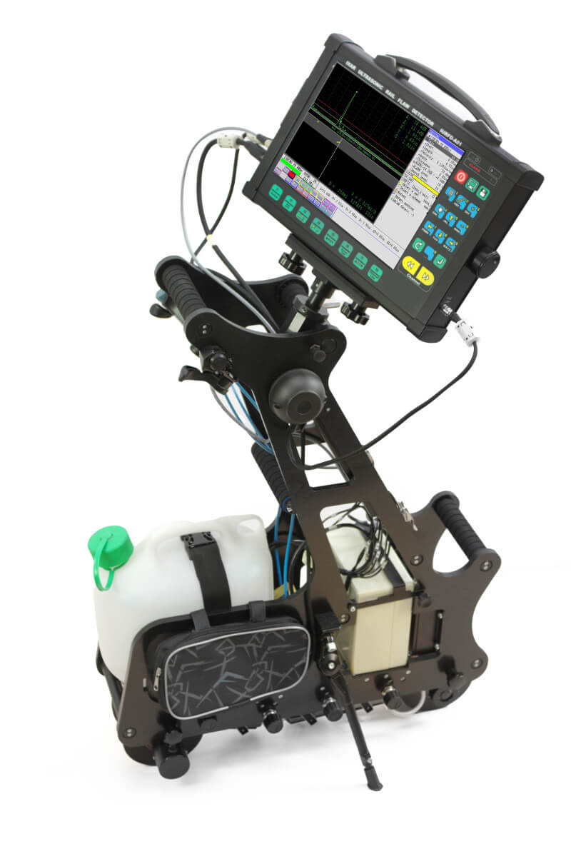
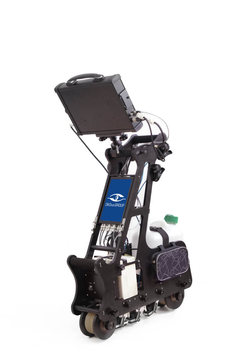
UDS2-77 ultrasonic single rail flaw detector is a hand-pushed cart intended for the inspection of one rail line. This rail inspection equipment is manufactured in 9 modifications and can use either Slide or Roller Search Unit with 3 to 13 UT channels (probes).
The rail flaw detector utilizes a unique scanning scheme that allows testing the entire rail section, except for foot flanges, by pulse echo, echo-shadow and echo-image techniques.
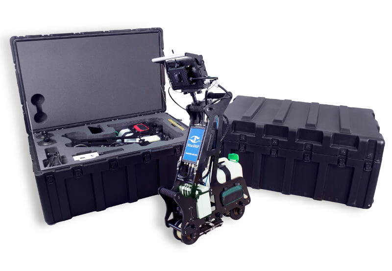
The cart is made from light but rigid composite materials, due to which the total weight of the device is 16 kg only.
User-friendly operation
Both mechanics (the cart) and electronics (the software) of UDS2-77 have been developed with due account for ergonomic design, user-friendly intuitive interface, as well as severe weather conditions that may occur while working on a railway track.
Key features
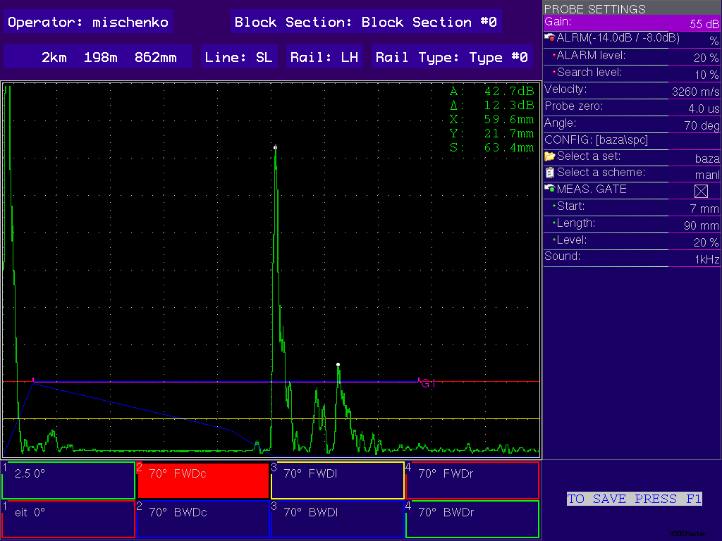
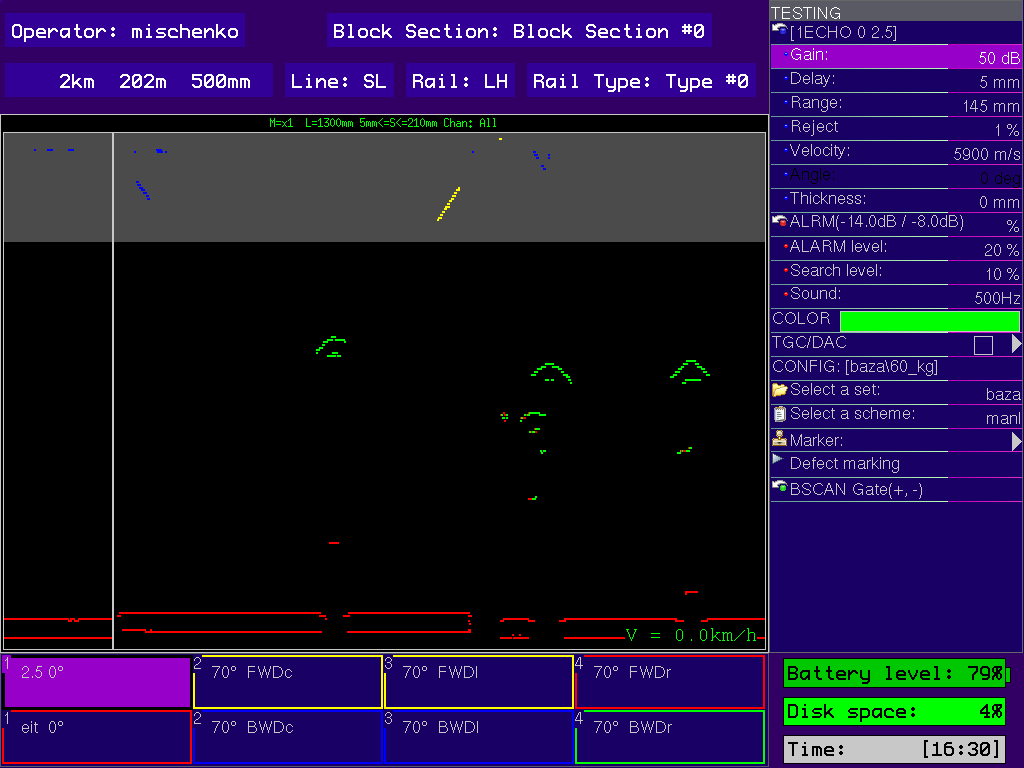
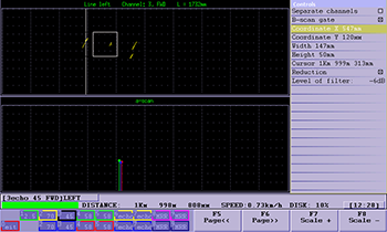
Representation of test results in the form of A-scan, multi-A-scan, B-scan for all channels;
Real-time display of test results in the form of B-scan;
Data recording and saving (operator’s name, line, direction, track number, left/right position, initial track coordinate, date, time, final track coordinate);
Screenshot saving (PrintScreen);
Saving of test results in the form of data array (B-scan) to the internal memory;
Use of USB flash drive for transmitting the test results to PC;
Availability of measuring gates in A-scan & B-scan modes;
Post-viewing of test result on the flaw detector with the possibility to measure conditional sizes of defects;
Possibility to put the track markers (e.g. “Bridge”, “Crossing”, “Bolt hole”, etc.).
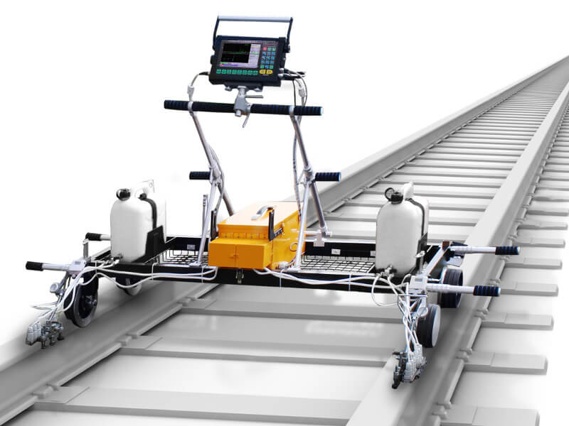
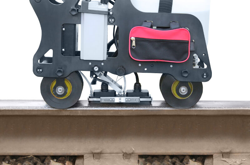
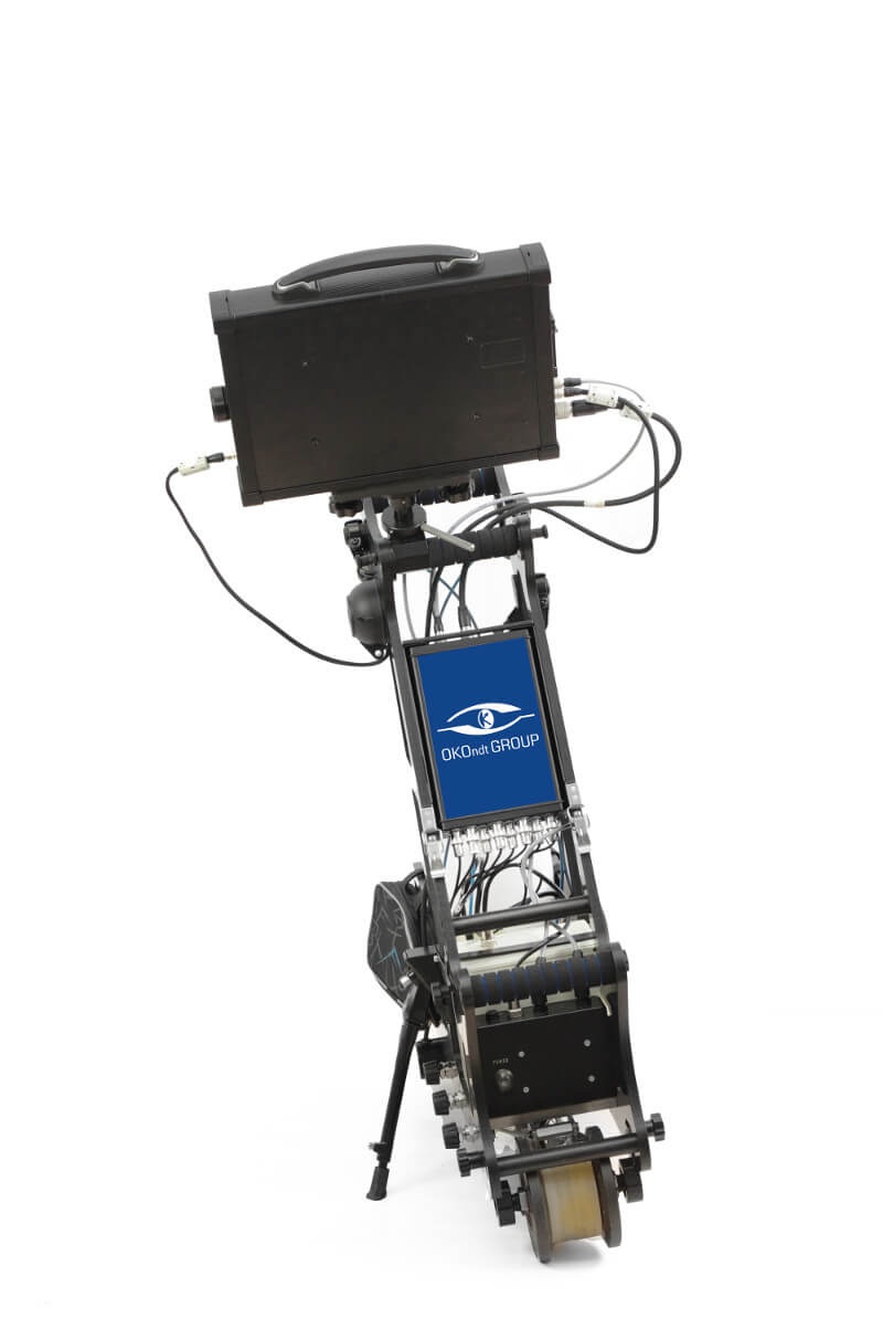
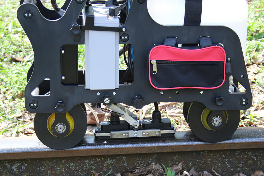
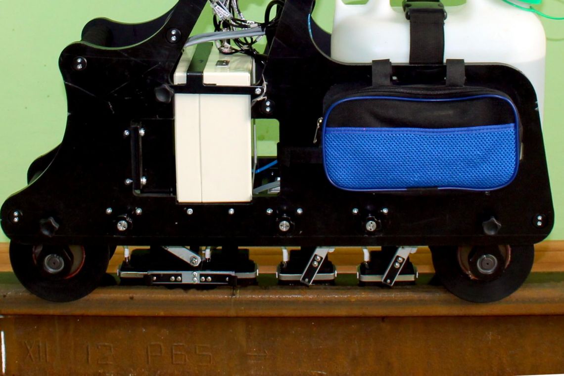
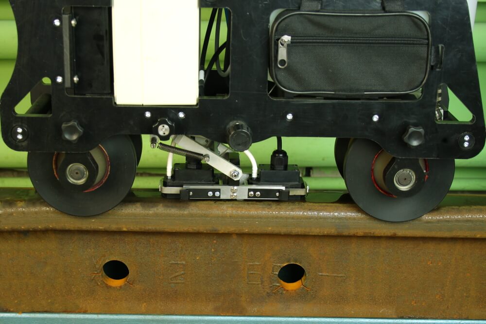
Trolley design
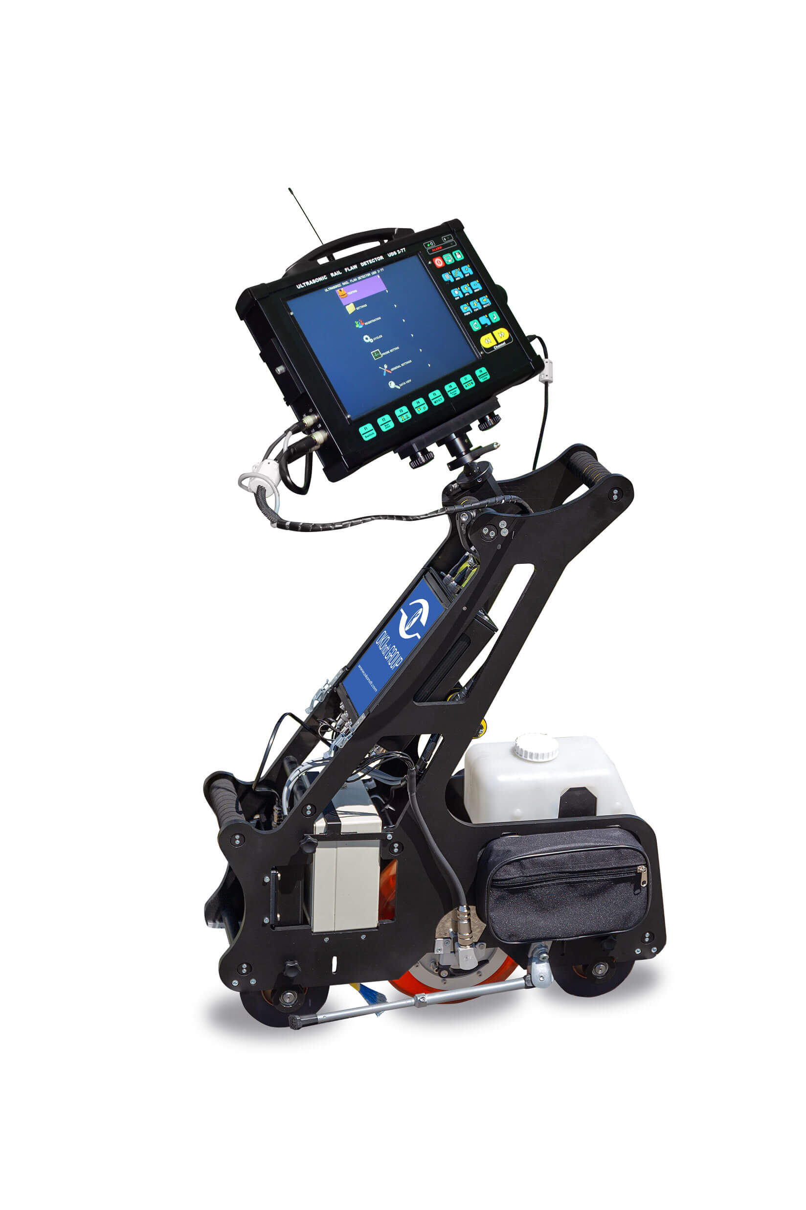
1. Weight of the trolley is 16 kg only.
2. Modular design of the trolley consists of a support frame with adaptive rollers; electronic unit for control and visualization; multichannel unit; battery pack; couplant (water) tank; probe units; suspension mechanism of the probe units to place them into operation/transportation position; encoder.
3. Position of electronic unit for control and visualization can be adjusted along three axes.
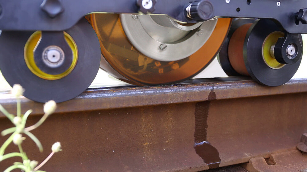
4. Probe unit (slide or roller) is transversely positioned in relation to a rail with the help of a dedicated control device.
5. Probe unit can be centered using adaptive rollers.
6. Suspension mechanism of the slide probe unit ensures a stable acoustic contact if the cart is tilted up to 150.
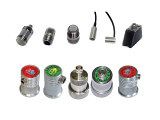
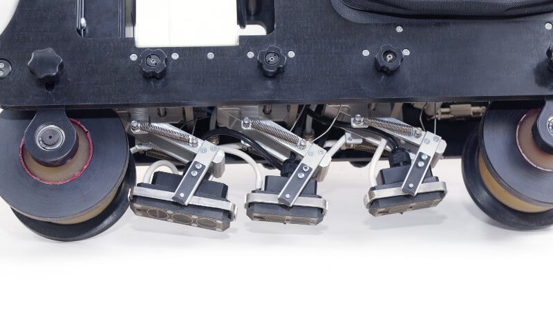
The Flaw detection cart can employs two types of Probe units
Conventional-type contact Probe Units with both standard and specialized probes are used in UDS2-77 flaw detector.
The probe units are made from wear resistant plastic material, with hard-metal inserts on the working surface.
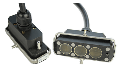
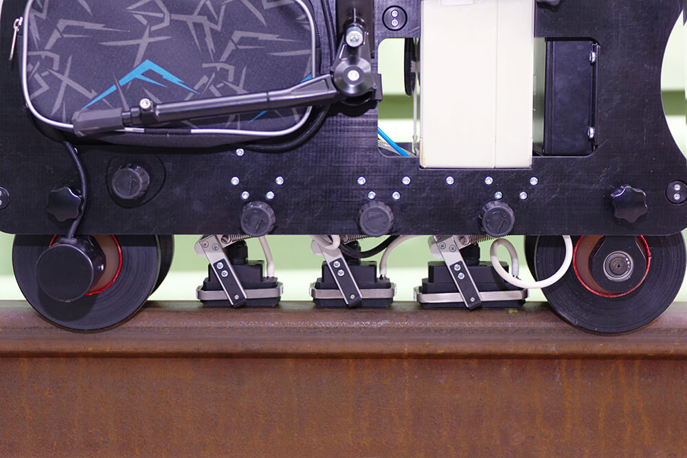
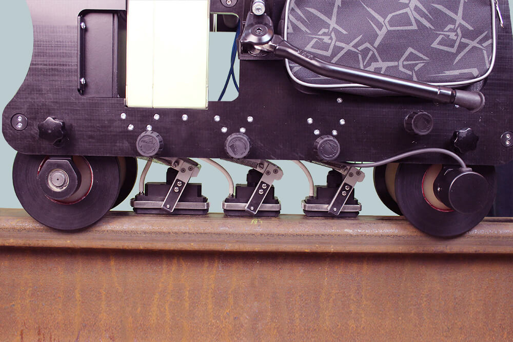
Fig. 2 — Slide probe units
Fig. 3 — Roller search unit (with immersion probes) of hand-pushed cart for ultrasonic rail inspection.
The slide probe units comprise the following probes:
| Probe unit №1: | Probe unit №2: |
| 00 probe — 4 MHz | 4х580х340 probe — 2.5 MHz |
| 700 probe — 2.5 MHz (Forward) | 700 probe — 2.5 MHz (Backward) |
| 4х580х340 probe — 2.5 MHz | 2х450 probe — 2.5 MHz (Forward/Backward) |
1. One 4 MHz probe, refracted angle 00 is intended for inspection of the entire rail section by height in the web projection, for the presence of internal defects and laminations. This probe enables two testing techniques: pulse echo and echo-shadow.
2. Two 2.5 MHz probes, refracted angle 700(one of them emits along, and another — across the trolley movement) are intended for inspection of the central part of the rail head, for the presence of mature transverse defects.
3. Two 2.5 MHz probes, refracted angle 450(one of them emits along, and another — across the trolley movement) are intended for inspection of the entire rail section in the web projection, for the presence of internal defects, as well as for inspection of bolt holes for the presence of star-type defects.
4. Eight 2.5 MHz probes, refracted angle 580 that are turned by 340 in relation to the rail axis. The probes are placed in two cases, with 4 piezoelectric-crystal plates each. These probes enable pulse echo and echo-image techniques, and are intended for flaw detection across the entire rail head.
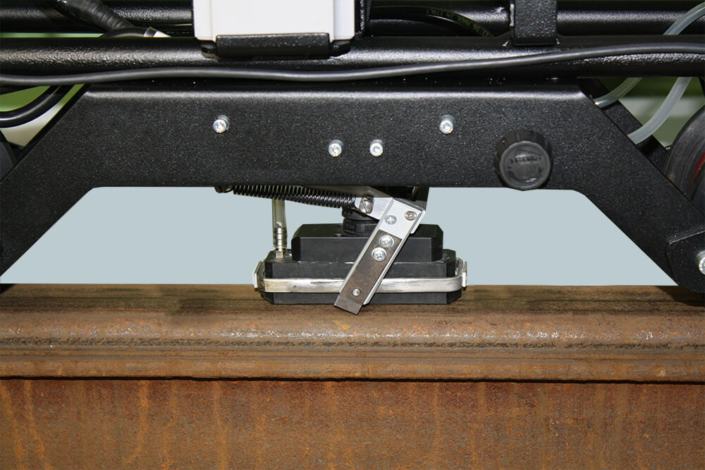
Suspension mechanism of the Slide Search Unit
Suspension mechanism is responsible for positioning the probe unit (slide) in the rail head cross section. It also ensures a steady acoustic contact when the cart is turned by ±150.
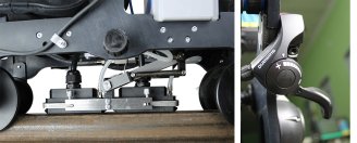
Fig. 4 — Suspension mechanism. Working position (lever down)
Fig. 5 — Suspension mechanism. Transport position (lever up)
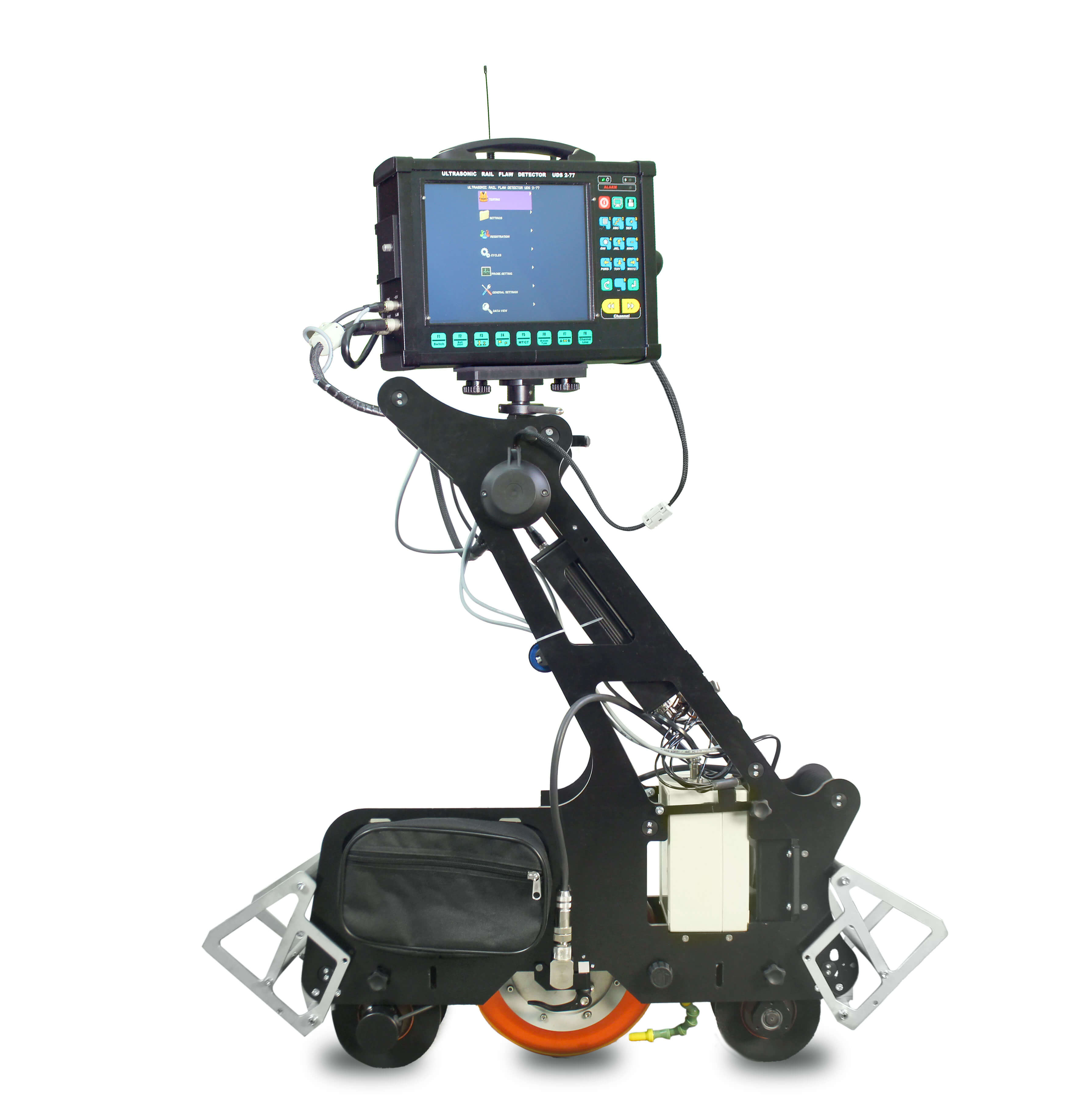
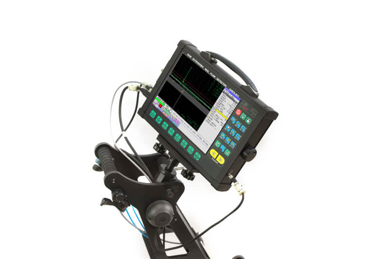
Electronic Unit of UDS2-77
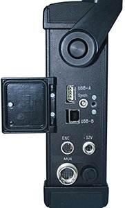
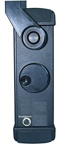
Fig. 6 — Side panels of Electronic Unit
For NDT inspector/operator’s convenience, the Electronic Unit of the flaw detector includes:
Navigation panel
1 — Control Knob to change operation modes and parameter values in the software interface;
2 — Connector for headphones;
3 — Connector for USB-drive;
4 — Connector for Encoder;
5 — Connector for Multichannel unit.
6 — Keypad of UDS2-77 flaw detector consists of two navigation panels that are used for browsing through the menu items, modifying the parameter values, and calling for various operation modes with the help of ‘hot’ keys.

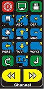
Hot Keys panel
UDS2-77 is featured by a simple menu structure for setup and calibration, as well as setting of software functions/modes. The device is furnished with Hot Keys panel to get an immediate access to main operation modes, such as display (А-scan/B-scan), correction of track coordinate, generation of test report, On/Off button for test results saving mode.
Find more about Visualization of the rail ultrasonic testing results here
A-scan
B-scan
Multi A-scan + B-scan
Fig. 7 — Test results display modes:
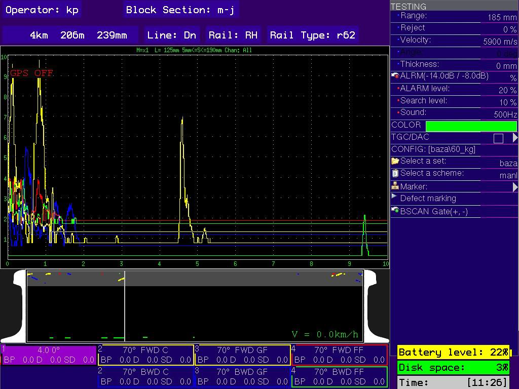
Test results post-viewing mode
a) General menu viewing
b) Flaw parameter measuring
c) B-scan + A-scan viewing
Fig. 8 — Test results viewing mode
Type#1 (Advanced version)
allows testing central and field faces of the rail head for the detection of internal and surface defects (head checking, Squat):
- Probe Unit 1 (Central Line):
- 0°-4 MHz
- 70°-2.5
- 4x58°x34°-2.5 MHz
- Probe Unit 2 (Central Line):
- 4x58°x34°-2.5 MHz
- 70°-2.5
- 2x45°-2.5 MHz
Type#2 (Wheel probe)
- Probe Unit 1:
- one 0-degree transducer, 2 or 4 MHz
- two 45-degree transducer, 2 MHz
- six 70-degree transducers, 2 MHz
- two 55-degree transducer, 2 MHz
Type#3 (AREMA)
allows to detect all defects in the rail, according to the requirements of AREMA.
- Probe Unit 1 (Central Line):
- 0°-4 MHz
- 70°-2 MHz (Forward Central head)
- 70°-2 MHz (Backward Central Head)
- Probe Unit 2 :
- 2x45°- 2 MHz (Forward / Backward Central head)
- 2x50°- 2 MHz (Side looking)
- Probe Unit 3 (Gauge side):
- 70°-2 MHz (Forward Gauge face head)
- 70°-2 MHz (Backward Gauge face head)
- Probe Unit 4 (Field side):
- 70°-2 MHz (Forward Field face head)
- 70°-2 MHz (Backward Field face head)
Type#4 (Indian version)
allows testing the rail head with 70° probes and testing for the detection of exclusively horizontal cracks)
- Probe Unit 1 (Central Line):
- 0°-4 MHz
- 70°-2 MHz (Forward Central head)
- 70°-2 MHz (Backward Central Head)
- Probe Unit 2 (Gauge side):
- 70°-2 MHz (Forward Gauge face head)
- 70°-2 MHz (Backward Gauge face head)
- Probe Unit 3 (Field side):
- 70°-2 MHz (Forward Field face head)
- 70°-2 MHz (Backward Field face head)
Type#5 (BASIC)
testing of the rail in the web projection
- Probe Unit 1 (Central Line):
- 0°-4 MHz
- 70° 2 MHz
- Probe Unit 2 (Central Line):
- 70° 2 MHz
- 2x45°- 2 MHz
Type#6 (EU)
testing of the rail in the web projection, except for the bolt holes, for the detection of “Star” defects)
- Probe Unit:
- 0°-4 MHz
- 70°-2 MHz
- 70°-2 MHz
Type#7 (Crane version)
Crane rail testing
- Probe Unit 1 (Central Line):
- 0°-4 MHz
- 70°-2 MHz (Forward Central head)
- 70°-2 MHz (Backward Central Head)
- Probe Unit 2 (Gauge side):
- 70°-2 MHz (Forward Gauge face head)
- 70°-2 MHz (Backward Gauge face head)
- Probe Unit 3 (Field side):
- 70°-2 MHz (Forward Field face head)
- 70°-2 MHz (Backward Field face head)
UT techniques: pulse echo, (echo image) and echo shadow.
Number of ultrasonic channels for 100% scanning: 13.
Nominal test frequency: 1 to 6 MHz.
Distance between probe pulse sendings: 1 mm at motion speed up to 5 km/h.
Variation range of receiving path gain: 0 to 100 dB, with a step of 1 dB.
Memory capacity for data storage: not less than 8 Gb.
Weight of the flaw detector without battery and couplant: up to 16 kg.
The flaw detector is powered by an independent power source (battery) with the rated voltage from 10.8 to 14.6 V and rated capacity of no less than 18 А·h.
Time of operating mode setup: up to 15 sec.
Time of continuous operation of the flaw detector with a fully-charged battery: no less than 8 hours.
Protection rating: IP 64.
The following alarms are generated during flaw detection: light – separate for every rail and common (via all test channels); sound – separate for every rail and common (for a group of channels); visual, on the screen – separate for every rail and every channel.
GPS system is used to determine defect location coordinates on the track.